DEAR POLE BARN GURU: What is your method for spacing the poles on a pole barn, how do you line up the locations of each pole on a wall? This is for my boy scout Eagle project, a 32x36ft pole barn to be used for equestrian therapy. ANXIOUS IN AUSTIN
DEAR ANXIOUS: The best advice I can give you is found in the Hansen Pole Buildings’ Construction Manual, which I excerpt from on setting pole barn posts:
The building layout establishes exact reference lines and elevations. Care in layout makes construction easier and helps keep building square.
Building width and length are from corner post outside to corner post outside!
After all framing has been installed, finished framework will normally be 3” wider and longer than ordered or “call out” dimensions. Not paying attention to this will likely result in more effort during construction.
To start, stake out a “base” line string. This will become either the building front or side. If trying to align the new building with an existing structure, roadway or property lines, have the first wall line parallel to the reference point.
See Figure 1 below.
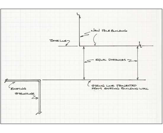
Figure 1
Locate and set front corner stake “A” along baseline. Drive a nail partially into stake top as a reference point. See Figure 2.
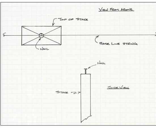
Figure 2
Hook a tape measure on nail at Stake A. Measure building length along base line from Stake A and set corner Stake B. See Figure 3.
Use a construction level (transit) and drive Stake B in so Stake A and B tops are level. Drive a nail partially into Stake B top at exact building length (as measured from column outside to column outside).
Figure 3
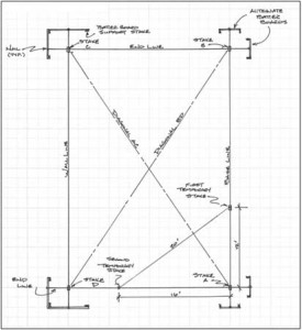
Next make endwall perpendicular to sidewall. Measure 12 feet along base line from Stake A and set a temporary stake. The intersection point 20 feet from this temporary stake and 16’ from Stake A is perpendicular to base line. Set a second temporary stake at this point. (Figure 3)
Measure outside building width along this line and set Stake D. Drive Stake D into ground…level with Stake A and B tops. Drive a nail partially into Stake D top at exact outside building width. (Figure 3)
From nail in Stake D top, measure outside building length. From nail in Stake B, measure outside building width. At the two measurement intersection, drive last corner Stake C, with top level with earlier three corner stake tops. As before, partially drive a nail into Stake C top, at exact outside corner point. (Figure 3)
Before proceeding, make certain all four corner stakes tops are level. Then double check, in this order – baseline length (A to B), Width B-C and A-D and then length C-D. Adjust nails or stakes B, C, or D as needed.
Diagonals AC and BD are to be equal for a rectangular building. Adjust by shifting C and D along rear wall line.
Do NOT move A or B.
Keep widths B-C and A-D equal. Recheck any shifted stake levels.
Drive batter board stakes 8 to 12 feet from all corners. If batter board materials are not provided with your building kit, girts make excellent batter boards, as long as they are not cut or otherwise damaged. The batter boards provide a level reference plane for building layout. Place so as not to interfere with excavation, pre-mix deliveries or construction and remain undisturbed until columns are backfilled.
Level and fasten batter boards to stakes at same heights as corner stake tops.
Stretch building string lines between batter boards, barely touching nails on corner stake tops. Partially drive nails into batter board tops to line up string lines.
The temporary and corner stakes can now be removed. Corners will be located where lines cross.
Photo above shows corner column in hole with batter boards in place.
Measuring along building lines, use small temporary stakes or nails painted with fluorescent paint to mark each post location center. Remember to locate the post center, ½ post thickness inside string lines. (Example: 5-1/2” post, post center is 2-3/4” inside string lines.)
See Figure 4.
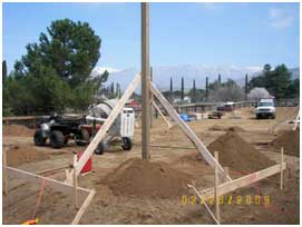
Figure 4
Figure 4 shows post centers as compared to “outside” building line.
After post centers have been located, offset (move) building line strings 1-1/2” (skirt board width), from post face outsides.
Why offset string lines? While this may sound confusing, not offsetting string lines could result in finished walls which are not straight, due to posts inadvertently touching lines. We’ve seen professional builders make this error far too often, and in this case, an ounce of prevention, is worth a pound of cure.
Once offset, building string lines will now measure 3” greater in dimension than building width and length (post outside to post outside).
Measure in from building string line 1-1/2 inches to set each post. Rather than having to use a tape measure each time, a 2×4 or 2×6 scrap block (which is 1-1/2” in thickness) can be placed between post and string line.
Now that you have the holes marked –it’s time to start digging holes!
Come back tomorrow for pointers on how to dig single and “multi-column”holes.
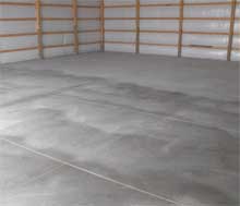 The most important things to avoid cracking where not desired is to have dedicated allowance locations for cracks (e.g. expansion joints or saw cuts should be located every eight to 12 feet for a four inch thick slab), have a properly prepared and well compacted site, eliminate sources of water which would or could flow under the slab, reinforce the slab (by use of one or more of the following – fiberglass strands, wire mesh, rebar) and to have the slab tied into the columns by use of rebar hairpins through the columns. The clean sand between the vapor barrier and the concrete should be moistened prior to the pour as well. Concrete mix with too much water in it will lead to future cracking. It is more work to pour with less water, but the end result will be far better. Keeping the slab well hydrated (water on top of the slab) for the first month after the pour will retard the speed of curing making the slab not only stronger, but also will reduce the cracking.
 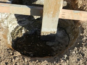 I found it strange – no posts were set on the front endwall of the building until after the balance of the building had been pretty much framed up. When those pole barn holes were dug, I watched as one of the crew members climbed into an overlarge hole to place a post. The hole could not possibly have been three feet deep! So much for frost issues. If you remember from yesterday – the frost depth here is 5 feet. They were only about 2’ short.
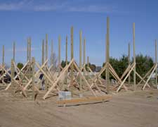 The Hansen Pole Buildings Construction Manual does address this issue in Chapter 2: “Grade change is ideally checked before placing building order, however this is not often feasible as a practical matter. If grade has not been checked before order placement, do so within 24 hours. Longer posts are far more economical when provided with original lumber delivery.”
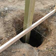 Confirm hole diameter from building plan. While usually 18-or 24-inch diameter, verify from building plans.
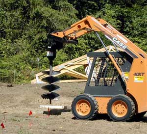 Using an auger mounted on a skid steer, bore holes to depth required on building plans. Holes slightly larger in diameter than auger bit can be created by first digging a pilot hole then offsetting auger slightly from hole center and boring again.
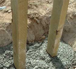 In cases where two adjacent posts will be located in close proximity to each other, the two holes may resemble a short “trench”. This is acceptable.
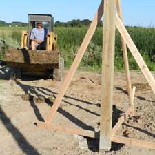 The building plans call out for the sidewall (double truss bearing) columns to be 6×8, with the six inch face oriented towards the sides of the building.


