Tag Archives: pole barn columns

Are My Columns Too Short?

Are My Columns Too Small or Too Short?

We receive and answer lots of questions. Even with a Construction Guide which extends over 500 pages, covering a plethora of topics and how to’s, there is always an unanswered question (sometimes two).

One of our good clients recently sent a query to the Hansen Pole Buildings’ wizardess of all things shipping, Justine, which I share now:

“Hi Justine, I received delivery of the columns for my building on Friday. After inspection, I had 2 questions that I’m hoping you can clarify for me because I don’t know if there is an issue with them. I also want to apologize in advance, because I know these questions are pedantic and probably nothing to worry about, I just want to make sure there’s no problem here since I haven’t been involved with the kind of construction that requires inspections before. 🙂

The building plans seem to have a slightly larger dimension than what was delivered. I’m sure the engineering has allowed enough safety margin that this won’t be a problem, I just don’t know if it’s going to be an issue on an inspection. For example, the corner columns are shown on the blueprints at 5 3/8″ x 4 1/8″ but the columns that were delivered are 5 1/4″ x 4 1/8″. So, you see it’s only 1/8″ on the long dimension of the column, but I don’t know if an inspector will have a problem with that. The same 1/8″ undersize dimension is true on the corner, endwall, sidewall, and shed columns.

I was under the impression that the length of the columns was a minimum length and not a nominal length that might be slightly less than that. It could also be that I have a misunderstanding about how the columns are spec’d. What I found is that the 14′ columns are all actually 14′ 1″, which is great, however all of the 24′ columns are actually only 23′ 10 1/4″ when measured to the shortest of the three laminated boards. They are all right at 24′ when measured to the longest of the laminated boards. This is only a concern of mine because I’m in the process of getting the site leveled out, but I’m currently at about 12″, which is cutting things pretty close on some of the columns. So, I didn’t know if the manufacturer made a mistake or if I just need to correct the way I measure them. My main concern is around ensuring I have full weight bearing on the notched post, which will only happen if I notch them at least 11″ down. I’ve attached a photo to show how I’m measuring them.”
To which our Technical Support Department cheerfully responded:

Thank you very much for sending us your concerns.

#1 You are going to find the dimensional lumber (2×4 through 2×12) provided can vary as much as 1/4″ plus or minus from the anticipated “ideal” dimensions. It is part of the randomness of dealing with an organic product (wood) which has to be milled. It is also why we are only able to use 40% of Pult (the ultimate strength of a material in a wood assembly) when engineering calculations are produced. In looking at the calculations for the long columns in the center of your building, for example, they are stressed to 92% using the “call out” dimensions. Using a Sm (Section modulus – depth of lumber squared x width of lumber divided by 6) of the 1/8″ under size, reduces the actual Sm by 1.64%, which would mean the member would be stressed to 94% under maximum design load.

#2 Column lengths do vary slightly due to the material lost in finger jointing. On the 20′ eave raised center section, with the bottom of the column at 32″ below grade, the amount of column needed would be 22’8″. With a column length of 23’10-1/4″ you could have as much as 13-3/4″ of grade change and still have plenty of column.

If you do happen to have a foot of grade change, it would be my recommendation to have the site brought closer to level before setting columns. Good compactable fill is not inexpensive. Reducing the grade change from 12″ to say four inches, as an example, saves 27 yards of fill across just the footprint of your building.

Please do not hesitate to reach out to this department further with any technical questions.

Rebar Hairpins

When I began writing these articles a few short years ago, I assumed I would run out of subject matter after about 100 or so. Silly me – as I’ve now produced in excess of 1100 of them and I keep realizing I have totally skipped over some obvious subject matter.

One of those which has been totally missed by me is rebar hairpins.

So, what is a rebar hairpin?

A rebar hairpin is a piece of rebar (https://www.hansenpolebuildings.com/2016/01/rebar/) , in the case of a Hansen Pole Building, ½ inch in diameter and five feet in length. An oversized (5/8 inch diameter) hole is drilled through each column, 1-3/4 inches above grade and two inches in from the outside column face. The rebar is inserted into the column so an equal distance remains outside of each end of the hole.
The two rebar ends are then bent towards the interior of the building, at a 45 degree angle to the pressure preservative treated splash planks. When the nominal four inch thick concrete slab is poured inside of the building, the hairpins will be in the middle of the slab’s depth – effectively tying the columns and the concrete floor together.

Why might the hairpins be important?

Embedment formulas.

Not baby, or racing formulas.

Part of the calculations for every post frame building should be those for column embedment. There are two conditions of embedment – non-constrained, where the building will never have a concrete floor or the concrete floor and the columns will be affixed to each other. The other condition would be constrained where the building columns are “constrained” from lateral motion due to the contribution of the concrete slab on grade.

There are cases where the building columns being constrained can actual save money (sometimes significant amounts). This is due to the shear forces the building must resist are reduced to 75% from the contribution of the slab constraint.

When wind forces are relatively high, building is tall and/or the building length to width ratio is large, the savings in column sizes and additional materials for shearwalls can amount to significant savings.

Hairpins also function, in frost country, to keep the columns and slab from being moved at different rates due to the forces of frost. This should be negligible on a properly prepared building site.

And there you have it… everything you wanted to know about rebar hairpins, and a little more.

How to Untwist a Pressure Treated Post

This actually began as an “Ask the Pole Barn Guru” question:

DEAR POLE BARN GURU: We have installed the Pressure Treated Posts  and they were straight when the concrete was poured, now a couple of weeks later we are seeing the poles twist and warp. They are straight at the ground level but about half way up they start warping. We are getting ready to put the Trusses up and want to try to get the twist and warp out as much as possible before the trusses are secured to them. What should we do for this issue? SHERI IN BENTON CITY

Twisted PoleThe series of photos on untwisted pressure treated posts are thank to Tim Fieldsend who had the very same problem back in 2003. Tim is my hero for having saved these photos for a dozen years!

When Tim contacted me with his challenge, I suggested a fix which I had not tried before, but it made some sense at the time.

The first step was to absolutely saturate the pressure treated post with water – soak it and keep it wet. Tim was creative enough to actually wrap a soaker hose around the columns!

Twisted Post
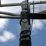
After a few days of being watered, apply significant and steady pressure on at the top of the column, in the reverse direction of the twist. Tim’s solution sure worked, however a substantial steel bar or rod cabled or chained to the top of the column would work as well. If the post is not thoroughly saturated, there is a high probability it will snap off. As the column begins to untwist, continue to tighten the cable attached to the lever arm.

Twisted Post
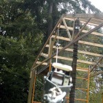
Once the column has been restored to straight, keep the tension on the cable and allow the column to thoroughly dry. Once dry – get the column incorporated into a completed building as expediently as possible.

One Pour Reinforcement Cage

The original Hansen Pole Buildings column encasement design, had the pressure preservative columns placed to the base of an augured hole. Pre-mix concrete was then poured around the lower 16-18 inches of the column to form a bottom collar. The bond strength between concrete and wood was sufficient to enable the assembly to resist both gravitational forces (settling) as well as uplift.

For further reading on the concrete to wood bond strength: https://www.hansenpolebuildings.com/blog/2013/04/pole-barn-post-in-concrete/

There were, however, a few Building Officials who just could not wrap their heads around this as a design solution – they wanted to see concrete underneath the columns.

The solution – we changed our design so the base of the columns “float” eight inches from the bottom. By nailing one of the framing members temporarily across the column, at the appropriate depth, it makes for a relatively easy design solution.

By doing this, premix concrete can be monolithically poured into a bottom collar which also provides a concrete footing beneath the column.

footing cage
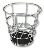
I’ve found what may be a quicker and easier solution. Pro-footer® manufactures a patent pending product called the “one pour reinforcement cage”. The cage rather reminds me of my futile days smacking golf balls around at the driving range – as a similar wire basket was used for practice balls.

The one pour reinforcement cage base is designed to ensure a solid footing when placed in the hole. Six inches up from the base is a relatively open platform which supports the bottom of the column as well as allowing six inches of concrete to flow under the base of the post, during a single pour.

The Pro-footer™ cage increases the shear and tension strengths developed by the concrete and reduces cracking of the concrete. It is the design of the Pro-footer™ to keep the spacing between the cracks in concrete minimized in order to limit crack width. The width of any such crack is controlled by the proper provision of reinforced concrete provided by the Pro-footer™ wire cage.

Besides the advantage of providing a relatively simple monolithic concrete pour, the Pro-footer™ cage is relatively inexpensive. They are easily applied in the field, their light weight makes them easy to handle and their use does not expose the interior of the column to potential decaying elements, such as occurs in cases where people drill holes through the embedded portion of the column for rebar.

I don’t often find myself attracted enough to a new product to say I would give it a try myself – however the Pro-footer® one pour reinforcement cage could be an exception!

Hard Rock Clause

When I was first constructing pole buildings, I found out the hard way why it is essential to have a clause in my agreements which covered the unknown – also known as “what you can’t see below the surface”.

rock clauseIn my case, we had contracted to build a 36 foot wide by 60 foot long horse stall barn – so there was a plethora of holes to be dug. Depending upon which hole we were at, 12 to 18 inches below the surface we hit a huge shelf of granite. Under the entire building!

After five days of renting an excavator with a ram hoe attachment, we finally got the holes dug, as well as losing any profits we ever anticipated making on the project!

What got me onto this subject is a recent project Hansen Pole Buildings supplied for Wallace Brothers Construction, Inc. (https://www.hansenpolebuildings.com/builders/portland-or-contractor.php). Ritchie Wallace was concerned about hitting rock at the site, and we asked him if he had a “hard rock clause” in his agreement with his client – which he did.

A fair hard rock clause covers both parties. It allows the builder to recoup extraordinary expenses due to one thing which cannot be controlled – what is underground. It also keeps new building owners from being taken advantage unfairly.

Granted, it has been 15 years since I was building, but for the benefit of all concerned, I will share the language we used:

“Purchaser shall absorb all costs incurred from unknown conditions such as rock removal, poor digging conditions, or poor soil bearing capacity; including but not limited to jackhammer, backhoe or auger rental (plus delivery and operator charges), sonotubes (plus delivery and installation) or dynamiting.”

“Seller’s price allots a maximum average of 30 person-minutes per column hole for hand-digging or 10 equipment minutes per column for auguring, with excess time to be paid for by Purchaser at a rate of $90 per person hour, or every portion thereof, for all office or administrative time and $60 per hour for project managers, superintendents, carpenters, laborers, etc.”

Weirdly enough, we never had to charge any client under this hard rock clause – as the few rare instances where issues came up, the clients always opted to take care of the issues themselves!

Whether a pole building contractor, or hiring one, I strongly encourage making certain this possibility is one which is negotiated in advance.

Just like the adage, “good fences make good neighbors”, a fairly written contract makes for good times between builders and building owners. When in doubt, get it in writing

Pole Barn Detective: Is it a Glulam?

Is it a Glulam?

Usually the process works this way – check with the Planning Department to confirm the desired building can be constructed on the property, have pole building plans prepared by a registered design professional (RDP – engineer or architect), apply for and be granted a Building Permit, then build.

The photo of the inside of this particular building, is a case where the building owner skipped steps 1, 2 and 3 going directly to #4. The building owners problems came – when they needed to get a permit for electrical and oops!!

Just in case anyone was wondering, this is NOT a Hansen Pole Building kit package.

Anyhow – the Building Official is now questioning the posts used in this building (see photo).

Is It A Glulam?In case anyone is even wondering, the column shown is NOT a glulam. What we are looking at, is six pieces of 2×6, which have been glued together with construction adhesive. Quality control, as far as aligning the 2×6 members, was not necessarily high on the list of important things when they were assembled. The alignment issue is actually just one of aesthetics, not of functionality.

Now we are going to discuss structural functionality.

The glue can be discounted entirely, as construction adhesives are not designed for this type of structural application. What we have here is nothing more than a nail-laminated column,which does not qualify to call it a glulam.

In 1984, my academic post frame hero (Dr. Frank Woeste), was a co-author of a paper on “Nail Laminated Wall Columns from Dimensional Lumber” (see TRANSACTIONS of the ASAE Volume 27, Number 4, pp. 1127-1130, 1984). This paper reported the test results from nail-laminated columns, with internal non-reinforced butt end splices.

In their testing, the lower members were staggered two feet from each other, similar to the photo which probably used 8 and 10 foot long 2×6 on the exterior and a 6 foot in the center. Dr. Woeste used #2 Dense Southern Pine for testing (which is greater in strength than the #2 material found in the local lumber yard).

The plies were nailed together with 12d nails, in a specific pattern. They were placed with two nails every foot outside of the spliced area, and four inches on center in the four feet of splice zone (the area between the shortest and longest members). Each pair of nails was staggered from the previous pair, in a specific pattern.

Provided the columns in the photo are nailed adequately to match the testing (anyone interested in taking this bet?), the results of the test, adjusted downward from the difference in strength from the use of #2 grade lumber rather than #2 Dense, would probably be a fair approximation of strength.

The results from the column testing, compared the strength of the nail-laminated columns, to the values of 6×6 #2 Southern Pine solid sawn columns. The results of the tests showed the nailed up columns were only 64% as strong in bending, as a solid sawn column! The test results were compared against testing of other columns which used reinforced splices (either with 5” x 24” 20 gauge flat steel plate, or with pressed in “truss plates”). These comparisons demonstrate the discontinuous (non-reinforced) joint between the vertical members is the weakest link of the nail laminated wall columns.

While I do not know the dimensions or climactic loading of the building in question, I have seen another photo of this building which leads me to believe the building is 14 to 16 feet in height.

My opinion? Based upon what I can see, this building is going to require some serious structural engineered repairs to the columns, in order to be adequate to carry the loads.  And it won’t be cheap, the engineer fees nor the repairs.