Tag Archives: paddle blocks

Attaching Roof Purlins on Edge to Trusses

Attaching Roof Purlins on Edge to Trusses

Reader MIKE in MOUNT VERNON writes:

“If your purlins sit on top of your trusses in the middle of your building do they sit on top of the gable truss also or are they on the side of the gable truss with hangers?”

Most ‘West Coast’ (I use this liberally as it extends east into Montana and Utah) pole barn (post frame) buildings utilize a prefabricated roof truss on each side of widely spaced interior columns (most often 10’ or 12’ on center). At every roof purlin location, a short 2×6 block (known as a paddle block) is placed between these two trusses. Block length is equal to roof truss top chord thickness plus roof purlin size. With a 2×6 top chord and a 2×6 roof purlin, block length is 11 inches.

Paddle blocks are held in place by driving nails through truss top chords, into block’s narrow (1-1/2 inch) edge. Generally builders will use as many as three 20d (four inch long) nails from each side.

If your first thought was, “this is a lot of very large nails into a very small block”, you are absolutely correct. More often than not, nails will split paddle blocks, if not immediately, splits will appear over time.

Once in place, roof purlins are located uphill from the block. Purlins stagger at each truss, with first purlin attached to paddle block with two to four nails, then a second purlin is nailed to first, with nails extending into block as well.

Now, as many as 14 nails will have been placed into a single block, pretty well guaranteeing the paddle block’s inevitable failure.

Besides an obvious problem of splitting a paddle block with numerous nails, there are some other issues caused by use of these blocks.

Post frame building eave height is measured from pressure preservative treated skirt board bottom, to roofing underside at sidewall column outside. This means interior clear height, is reduced by thickness of any concrete slab, roof truss end thickness (heel height) AND (when purlins go over truss tops), roof purlin height. Having roof purlins over truss tops, costs usable space inside of building.

When using a structural design, where roof purlins overlap at each truss, roof steel cannot be pre-drilled. Pre-drilling has many benefits – perfectly straight screw lines and it makes it obvious to installers when a screw misses a roof purlin. With staggered roof purlins, all too often a leak occurs when this 1-1/2” offset at overlaps is not accounted for.

In paddle block scenarios, prefabricated roof trusses are spaced apart by 5-1/2 inches. Even though there are two trusses per column, they are not physically joined to each other. Paddle blocks are not creating a load transfer. As trusses do not load share, under extreme snow load conditions, weaker of these two trusses can fail, creating a collapse. When trusses are properly nailed together (face-to-face without paddle blocks), loads are carried by both truss pair members.

In your scenario, if (big IF) I was going to put purlins over top of interior (middle of your building) trusses, I would want to joist hang them into the side of end trusses, unless an end overhang was present.

ZIP Sheathing

ZIP Sheathing and Other Post Frame Thoughts

Reader SPENCER in WINLOCK writes:

“Hello, I’m in the planning phase and your roof purlin style and watching the “Hart and Home” youtube series have just about convinced me to go with Hansen buildings. I have a few general questions. 1. I have a tight driveway with a gate. What kind of a truck would 40′ trusses be delivered on? 2. I’d like to use zip panels on my walls and roof for sheathing below the metal. Is this something that can be added to the engineering package and supplied by me? I’m assuming the weight of the panels would need to be accounted for in the roof loading. 3. Are 20′ side walls a possibility with your buildings? 4. I’d like to use poured columns and wet set brackets for my footings. Is this something that can be added to the engineering package and supplied by me? My goal would be to have these installed well before taking delivery of the building. 5. I’d like to do a lean-to but need to keep as much roof height as possible for a 14′ door. Do these have to be designed with trusses or can I specify dimensional lumber? Thank you!”

Mike the Pole Barn Guru responds:

For those following along at home – Hart and Homes YouTube series can be viewed here: https://www.youtube.com/channel/UCjzEsuHQ8UFZEbXQc16RT9Q

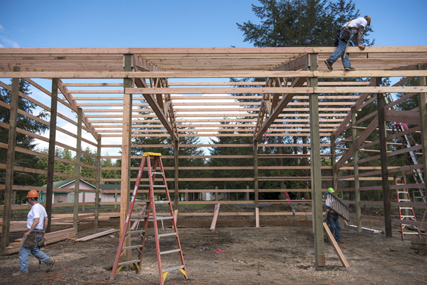
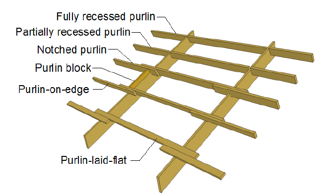
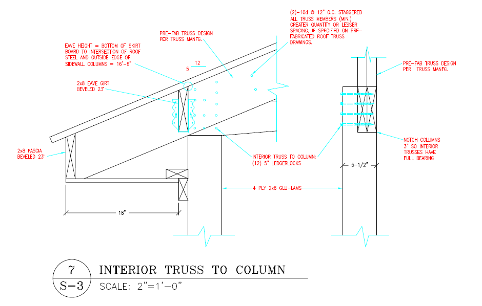
Hansen Pole Buildings has provided more fully engineered post frame buildings to our clients in Washington State (roughly a 1000 at last count), than any other state. Mr. and Mrs. Hart are a great couple and have been a pleasure to work with. This roof purlin style (purlins on edge) is fairly typical in Western U.S. post frame buildings, however, recessing them between trusses with joist hangers is not. Our feeling is this engineered connection is far superior to attaching purlins to a very small block full of nails (extended reading on paddle blocks can be found here https://www.hansenpolebuildings.com/2012/05/paddle-blocks/).

In answer to your questions:

1) Regardless of supplier, both roof trusses and steel roofing/siding are typically delivered by semi-trucks pulling 48′ trailers. You may want to make provision to have a utility trailer handy for at least a steel package to be off loaded onto, should you feel your entrance is just too tight for this sort of truck/trailer combination.

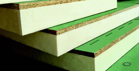
2) Zip System sheathing was introduced by Huber Engineered Woods in 2008 and it has been widely adopted in many U.S. states. Huber manufactures premium OSB products such as Advantech sheathing. Many builders prefer Advantech over plywood, due in part to quality problems they were seeing in plywood.

Zip System sheathing’s chief virtue is it marries a water-resistant barrier (WRB) to sheathing, eliminating the step of adding a separate WRB. Many builders like the Zip system a lot because it eliminates what has always been a troublesome step in building processes. This is, carefully installing large plastic sheets around an entire building, carefully lapping it at seams, and more carefully cutting and taping around doors and windows so it directs any water to the exterior.

While Tyvek (first popular building wrap), was originally marketed as an energy-saving material, it was soon disproven that a building with Tyvek, installed typically, wasn’t much tighter than a conventional building with asphalt felt.

A building built with Zip sheathing, however, taped and sealed as recommended, produces very tight results without a lot of fussing. This is especially true in relatively simple building plans without a lot of bumps, angles, and complex shapes.

Main Zip Sheathing downside is a heavy reliance on flashing tape. Huber makes high-quality tape in various widths and also makes a stretch version for window pan flashing and other tricky details. Still, water, frost, or dirt can undermine a watertight seal, as can sloppy installation.

Liquid-applied sealants offer an alternative to tape and is gaining in popularity. One example is Huber’s Liquid Flash, a thick liquid flashing applied with a caulking gun and spread with a trowel. Liquid flashing provides a nearly foolproof solution for waterproofing window pans, foundation joints, and other tricky or vulnerable transitions.

Like any product or system Zip sheathing has pros and cons. Some are actual and proven, some more theoretical. This product has not really been around long enough to stand time’s test. But, there are few in field failure reports and most contractors who have tried this system are happy with it overall.

Here are main arguments, pro and con:

Pros

  • Installs sheathing and water-resistant barrier in one step. Saves labor.
  • Makes it relatively easy to create a very tight shell.
  • This is a complete system with high quality tapes and liquid sealant, as well as published details backed by a reputable company.
  • Backed by a 30 year warranty, but not transferable, and subject to usual conditions about proper installation.
  • Window installation and flashing is easier than with building wrap (but relies on tape at window head flashing). Eliminates Origami style building wrap folding.
  • Quick dry-in for contractor with less concern about wind and water.

Cons

  • Tape must be installed carefully without dirt, frost, or moisture to seal well.
  • Horizontal seams are vulnerable to water penetration if tape fails. This is especially a concern at door and window tops.
  • Less permeable to moisture than most building wraps, so in theory the wall may not dry out as easily.
  • Not a true drainage plane, as can be created with draining building wraps. Vertical spacers or a second building wrap layer would be needed for a true drainage plane.
  • If nails are overdriven, especially “shiners” missing framing, OSB is exposed and needs sealing with tape or sealant.
  • More expensive materials (but savings on labor).
  • On a roof, especially, I would be reluctant to trust tape to prevent leaks, so would want another roofing felt or synthetic underlayment layer.
  • I would not want to screw roof steel to any OSB product.

Many builders like Zip system’s simplicity. To a large extent, its long-term performance depends on taped seam durability. If applied to a clean surface with a roller, as recommended, all indications are it will provide a long service life. This is a high-performance tape. Still,  it is partly a matter of faith it will remain water tight for decades.

Alternatively, building wrap does not last forever either. It tends to get brittle and deteriorate over time. It can deteriorate rapidly if it stays wet due to trapped water — for example, if a building wrap section gets bunched up behind a trim piece as I have seen around windows, corner boards and other exterior trim.

With any waterproofing product, workmanship quality is at least as important as material. A building built well with steel siding over plastic building wrap can perform as well as one with Zip sheathing. It just a careful detailing matter — especially  around doors, windows, and other joints prone to leakage.

With all of this said, yes, you could provide your own Zip sheathing and we can incorporate it in your engineer sealed plans.

3) We can provide eave sidewalls to 40 feet tall and three stories (50 feet and four stories with fire suppression sprinklers).

4) We engineer many of our buildings using poured piers and wet-set brackets. We typically provide brackets as ours have an ICC ESR Code approval and we ship them out to you far in advance of your building shell materials.

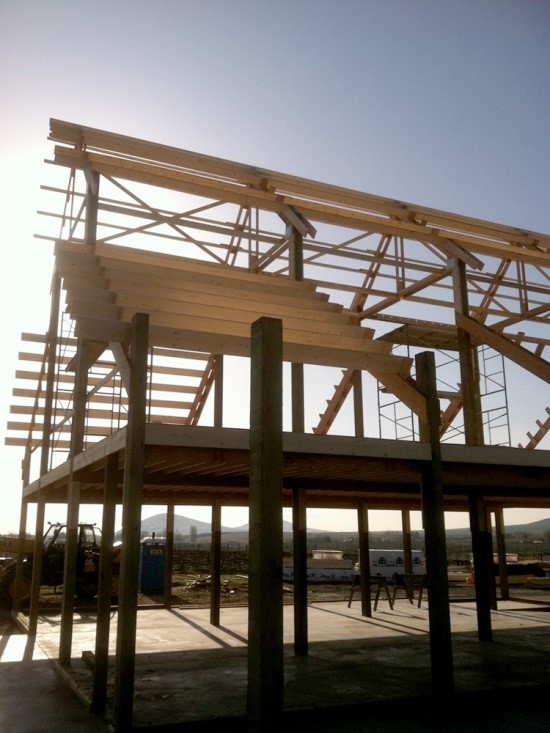
5) Our default for attached lean-to roofs would be rafters as opposed to mono-pitch trusses.

What Kind of Trusses Are Pictured?

What Kind of Trusses Are Pictured?

This question was posed by Hansen Pole Buildings’ Designer Doug. Photo isn’t of a Hansen Pole Building, probably raising questions in Doug’s mind as it looks rather foreign.

Only actual trusses in photo are in raised center portion of this monitor style building. Interior trusses were probably sold to building owner as being “double trusses”. In actuality this system has only a single truss placed upon each side of columns. These trusses, even though only inches apart, do not load share. They are only as strong as weakest individual truss. Between trusses, sticking up beyond top of top chords are paddle blocks (read about paddle blocks here: https://www.hansenpolebuildings.com/2012/05/paddle-blocks/) to attach roof purlins.

Monitor wings (or side sheds/lean-tos) have rafters placed each side of columns with paddle blocks as well. Second floor (aka loft) extends out into wing areas, although quickly loses functionality as headroom decreases close to eaves.

More headroom could have been garnered throughout entire second floor had trusses and rafters been positioned to allow roof purlins to joist hang into their sides. When placed as “top running” purlins, interior clear height decreases by purlin thickness. Positioning of roof trusses as lowered, below purlins causes builder to have to frame outriggers (or tails) above truss in order to support sidewall overhangs. Each paddle block makes for a purlin stagger and eliminates one’s ability to predrill roof steel panels. This adds to possibilities of roof leaks being created by each stagger point.

Other concerns exist in this photo. Where roof purlins overhang single end truss, attachment has been made with yet another set of paddle blocks. With an assumption overhangs will be enclosed, this allows for outside air to enter in spaces created between purlins. This decreases efficiency of dead attic space airflow from eaves to ridge.

Solid blocking should be placed between end overhanging purlins to provide continuity of a load path from roof diaphragm to ground. As being built, load path has been divided.

Perimeter beams in this photo show to be inset between the columns. My curiosity wonders how they adequately attach? Your guess is as good as mine.


Connecting Trusses Not Dots

Connecting Trusses Not Dots

This feature is probably not overly mentioned, however as most structural failures involve connections, it probably should be.

FEATURE: Double trusses notched into sidewall columns and connected with Strong-Drive® SDWS TIMBER Screws

BENEFIT: Trusses placed in a notch cannot slide down columns and Strong-Drive® SDWS TIMBER Screws resist uplift forces without a need for boring holes through columns.

WHAT OTHERS DO: A myriad of design solutions exist.

For trusses mounted every two or four feet upon truss carriers (headers between sidewall columns) attachment can be by toe-nail or engineered steel hangers to carriers. In some instances paddle blocks are inserted between carriers and trusses are nailed to these blocks.

With single trusses aligned with sidewall columns, trusses are most often placed into a notch cut into one side of columns. With nail or glu-laminated columns an interior column ply can be cut short to create an integral notch. Truss to column connections may include nails and/or bolts.

In designs with two single trusses, most often a truss is placed on each side of sidewall columns on top of bearing blocks. Bearing blocks may be nailed, lagged or bolted to column sides. Trusses are attached in same fashion as bearing blocks. Trusses are spaced apart along their length by paddle blocking installed between chords. Under extreme loading conditions trusses and their bearing blocks have been seen driven down sides of columns to rest upon building contents or even, the ground.

A variant on this places trusses closer together so they may be notched into sides of each column. This allows for elimination of bearing blocks and their associated challenges.

At Hansen Pole Buildings, we have trusses physically face-to-face nailed providing for a true load sharing between trusses. A notch is cut into one side of columns for trusses to bear. Attachment of trusses to columns is most often done by use of Strong-Drive SDWS Timber screws.

WHAT WE DID IN 1980: Lucas Plywood & Lumber placed a single truss upon each side of columns, on top of a nailed on bearing block. Trusses were attached to columns by means of a ¾” diameter, non-galvanized through bolt – entailing having to drill through nearly nine inches of wood and hoping to avoid steel connector plates at each truss heel.


Prefab Wood Trusses are Sexy

Prefab Wood Roof Trusses Are Sexy Though

In 1952, in Pompano Beach, Florida, an inventor named Carroll Sanford had been experimenting with building prefabricated roof trusses using plywood gusset plates and varying concoctions and combinations of glue, staples, nails and screws. Eventually he conceived of light gauge steel plates with punched teeth to connect wooden members.

If this wasn’t a sexy use of technology, then I don’t know what would be.

A burgeoning pole barn (post frame) building industry was largely aided by this new ability to economically clearspan relatively large distances.

What Hansen Buildings does now and since 2002:

FEATURE: Prefabricated face-to-face doubled roof trusses.

BENEFIT: Provides an engineered solution with clearspan widths of 80 feet and (in some instances) more. Endwall trusses make for quick and easy installation, while maintaining roof slopes.

True double trusses provide increased reliability due to their load sharing capabilities: https://www.hansenpolebuildings.com/2018/09/true-double-trusses/.

EXTENDED READING ABOUT THIS SUBJECT:

My all-time most read article: https://www.hansenpolebuildings.com/2011/06/pole-barn-truss-spacing/

Why most people should not order trusses: https://www.hansenpolebuildings.com/2018/10/why-most-people-should-not-order-trusses/

WHAT OTHERS DO: Another feature with a myriad of possible outcomes. I will defer “how” trusses are attached to columns for a later article.

Theories of roof truss spacing become most generally divided up geographically. These geographic nuances do bleed over from one area to next, so are not cast in stone.

Eastern U.S. places single trusses upon two or four foot centers attached to tops of truss “carriers” – headers spanning from sidewall column to sidewall column. Here are a few words about truss carriers: https://www.hansenpolebuildings.com/2018/10/what-size-truss-carriers/.

Midwest most often opts for a single truss aligned with sidewall columns. Spacing might be as little as 7’6” and as great as 10’.

Going West – expect a single truss each side of sidewall columns with paddle blocks to attach roof purlins. Learn about paddle blocks here: https://www.hansenpolebuildings.com/2012/05/paddle-blocks/.

While Eastern and Midwest post frame buildings generally feature trusses at each end. As one heads west, dimensional lumber rafters are often seen – relying upon building erectors to achieve proper alignment with interior trusses.

WHAT WE DID IN 1980: Back in green lumber land – Lucas Plywood & Lumber fabricated trusses out of green lumber. As spans (and dimensions of top and bottom chords) increased they became phenomenally heavy.For building ends, 2×12 #3 rafters were provided.


Spot the Post Frame Problem

Spot The Post Frame Problem – Reprised

In our last episode, I left you all with a cliff hanger. I did clue you into it being a structural issue, which rules out our builder in the air with his safety harness hooked to an invisible sky hook.
While you all ponder the photo and look at it closely, I will mention a few items which are not necessarily a problem, just maybe not what I would call “best practices”.

Note the trusses. One is on each side of the column. Chances are good this builder is marketing his product as a double truss system. What they actually have are two single trusses spaced 5-1/2 inches apart. These trusses do not act as a pair, because the blocking between them will not transfer the load from one truss to the other.

Each of those trusses is bearing on a block. The trusses are depending only upon the nails or bolts driven through the end of the truss and the blocks to keep them up in the air. There was a time when I did buildings this way also. Until the day I saw a set of trusses and the blocks below them driven down the sides of the poles by excess snow! They were only stopped from hitting the ground by the vehicles which were crushed inside.

Paddle blocks – if you do not know what they are, or their potential for future challenges, you will want to read here: https://www.hansenpolebuildings.com/2012/05/paddle-blocks/.
Okay, time to get serious here. Look at all the pretty wall girts. Nailed flat on the outside of the columns. They all fail due to not meeting the required deflection criteria set by the Building Codes: https://www.hansenpolebuildings.com/2012/03/girts/.

Now the particular jurisdiction where this building is being built has their own prescriptive solution to this problem. I’ve railed against prescriptive requirements in this forum previously: https://www.hansenpolebuildings.com/2012/02/prescriptive-requirements/. Look closely at the wall in the back of the photo. Look at the right hand bay. Note how every other wall girt has another board nailed to it to form an “L” as a stiffener. Truly wonderful as this solves the deflection issue for these particular girts only. The girt in between, without the stiffener, still fails!

Again I preach and beseech – please, if you are going to construct or have constructed for you a new post frame building, only do so with plans which are design specifically for your building and your building only, which are designed by a Registered Design Professional (architect or engineer).