Tag Archives: lateral bracing

Will I Need to Use Double Trusses?

Will I Need to Use Double Trusses?

Reader DALE in TOMPKINSVILLE writes:

“On an open front 5 bay tool shed, roof length 60 feet, width 40 foot, height of 10 foot, 12foot, trusses on 6×6 columns, 12/4 pitch located in southern Kentucky zone 6 will I need to double the trusses?”

Need and want are two different things. In all likelihood, single trusses will support your climactic loads. Double trusses do have some distinct advantages however.

ASABE (American Society of Agricultural and Biological Engineers) published ANSI/ASABE S618 “Post Frame Building System Nomenclature” in December 2010. For those who are unfamiliar ANSI stands for American National Standards Institute (www.ansi.org). ANSI is a private non-profit organization overseeing development of voluntary consensus standards for United States products, services, systems and personnel.

In ANSI/ASABE S618, a Metal plated connected wood truss would be described as, “A truss composed of wood members joined with metal connector plates (also known as truss plates). Metal connector plates (MCP) are light-gauge, toothed steel plates. The most common type of light wood truss.” Ganged wood trusses are defined as, “A truss designed to be installed as an assembly of two or more individual light wood trusses fastened together to act as one.”

nailing trusses
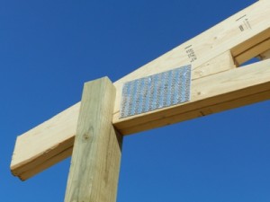
For Hansen Pole Buildings, any time we are using a “real” double (more specifically ganged) truss system, we specify top chords to be a minimum of 2×6, regardless of loads. I say “real” because placing a single truss along each side of a column is not a double truss. They are two single trusses, acting independently from each other. A true double truss system, such as used by Hansen Pole Buildings, features trusses physically attached face-to-face by means of mechanical connectors (e.g. nails, bolts, etc.). This allows for two members to actually load share, reducing probabilities of one weak single truss failing and pulling a roof system down with it.

True ganged trusses, due to their load sharing capabilities, often are able to utilize smaller steel connector plate, smaller or lesser dimension lumber for chords and/or webs, and require far less lateral bracing. Often utilization of two-ply ganged trusses results in a less expensive overall structural design solution, when all factors are taken into consideration.

Three sided buildings also pose their own unique set of structurally challenges, please read more here: https://www.hansenpolebuildings.com/2014/03/three-sided-building/

Problems in Steel Truss Building Land

Problems in Steel Truss Building Land

Disclaimer – Hansen Pole Buildings does not provide steel truss post frame buildings and I have never personally been involved in the structural design of one, however there are a plethora of readily evident challenges with this building which should be properly addressed.

Reader JAMES in TALLAHASSEE writes:
“I am framing in three sections of a five section clear span metal truss barn. In addition to the roof purlins on top of each truss there is a row of 2×6 lateral bracing running through the web of the truss. Can I remove the two that would be running directly through my framed wall? It’s not vertical but angled toward the peak so framing and siding around it will be trial and error. I even considered pulling it and using a steel cable to replace it. The ones I am speaking about are over each window in the picture but it is the opposite wall I am concerned about.” Mike the Pole Barn Guru writes
James ~

I will address your question first, then will share some challenges I see with your building – many of which should be addressed to the engineer of record (EOR) who sealed the plans for your building.

It is unlikely you would be able to safely structurally remove the braces, they keep the bottom chord of the truss members from bucking in the weak direction (towards the endwalls) under stress reversals caused by high wind loads. It might be possible to cut them and anchor them into each side of your interior framed wall, provided the wall is adequate to support the imposed loads. This is a question which would need to be posed to the EOR. AS for replacing the lumber braces with steel cable – not going to work. The cable would be strong in tension, however offers no resistance to compression. If the cables were to be placed in an X fashion (going from top of one truss to bottom of the next, as well as bottom to top) it might be possible, however again poses engineering and connection challenges which should be addressed by the EOR.

Moving on to some structural problems I see with your building (again all of these should be addressed directly to your EOR as he or she has placed their seal on the plans and have ultimate structural responsibility)….

As best I can tell, the columns and steel truss frames of your building are placed every 12 feet. If they are over 10 feet apart, a single 2x member as bottom chord bracing is inadequate – under load they will buckle in the weak direction. Solutions could include – adding a 2×4 to the top or bottom of the 2×6 to form either a T or an L. Typical attachment would be with a 10d common nail, generally at 12 inches on center.

It appears your building has 12 foot sidewalls, if so engineering is required to design the size and spacing of the studs in your walls. You have a serious problem in your endwalls – code requires the studs to run from the bottom plate to the roof line continuously. In your instance, a hinge point has been created at the plate line running across the endwall at eave height. Without some serious engineering analysis to brace this point, your endwalls will buckle at this point under windloads – generally being sucked outward.

I am also seeing “air” between the roof purlins where they cross the endwall truss. In order to adequately transfer the wind shear loads from the roof to the endwalls – solid blocking is required between the purlins at the endwall.

In the event an engineer was not involved in the original design of your building, I cannot recommend strongly enough for you to hire a local Registered Design Professional (engineer or architect) who can physically visit your building and provide structural solutions for the challenges visible in your photo, as well as others which may not be readily evident from our limited viewpoint. I am not trying to get you to spend your hard earned dollars for naught, I would just like to make sure your building stays upright in the next wind event.

Can I Remove Bottom Chord Bracing?

Truss Bracing In The Way?

Thirty three years ago, when I first dipped a toe into the post frame industry, roof truss bracing was pretty much an afterthought. Even though I came to pole buildings from the prefabricated metal plated truss business, bracing (especially of bottom chords) was pretty much a subject left up to the person doing the building.

Back then, it was not unusual to see 40 foot and wider spans, with absolutely no bracing at all between pairs of trusses spaced every 10 to 14 feet.

Apply a bit of a load to those trusses, from either wind or snow, and the bottom chords begin to form an “S” curve, as they are buckling in the weak direction.

Bottom Chord BracingSolution to the S? Add bracing.  

Modern engineered prefabricated roof trusses do take into account and recommend bracing. Oddly, the drawings will specify what appears to be a single 2x lateral brace, on truss spacings greater than 10 feet. Why I say “odd” is because a single 2x brace, of any size, which spans over ten feet, will buckle in the weak direction just like the trusses did.

Roof truss bottom chord bracing, properly designed and installed will not only keep the trusses in plane (standing upright), but will also brace the endwall columns. By the use of strategically located X bracing, loads from the endwalls and truss bottom chords can be transferred into the roof diaphragm.

A “load path” must be created from one end of the building, to the opposite end.

For example: a 60 foot long building, with five equal sidewall column spacings (or bays) of 12 feet each. Bays one and five are braced with X’s from the end truss bottom chord to the top chord of the second pair of trusses; and from the end truss top chord to bottom chord of second pair of trusses. Common sense says this is a fairly rigid bracing system as both directions take the loads into the plane of the roof.

In bays two, three and four, lateral bottom chord bracing is applied in the plane of the bottom chords. This bracing is anchored to the relatively “stiff” first and fifth bays.

Let’s complicate matters….

Imagine bay #3 has a large door, through which building owner desires to drive a vehicle in, place on a car lift and raise it so it is between the pairs of trusses. Wonderful, until the vehicle hits the truss bracing.

Oops….

Solution: remove the lateral bottom chord bracing in bay #3 and change the bracing in Bays #2 and 4 to X bracing. Every truss is still braced in both directions, and the load between the second and third pairs of trusses is transferred by the roof diaphragm.

If the building is designed by a RDP (registered design professional – architect or engineer), it is essential this modification be ideally made in the initial bracing design, so as not to incur additional engineering fees for a change.

Obviously this solution will not work to remove lateral bottom chord bracing in adjacent bays, but it does afford some added flexibility in design solutions.