Tag Archives: International Building Code

Section Modulus (Sm) for Lumber

Section Modulus (Sm) for Lumber

Nearly a decade ago I penned an article explaining lumber bending stress: https://www.hansenpolebuildings.com/2014/08/lumber-bending/

After 10 years, a reader nicely told me I did not explain where some terms in this article come from. One of these is Section Modulus (S or Sm in calculations). Let us take a visit to the National Design Specification (NDS) for Wood Construction developed by the American Wood Council’s (AC) Wood Design Standards Committee. This publication has been approved by ANSI (American National Standards Institute) as an American National Standard.

ANSI is a private nonprofit organization overseeing development of voluntary consensus standards for products, services, processes, systems and personal in the United States. It also coordinates U.S. standards with international standards so American products can be used worldwide.

ANSI accredits standards developed by representatives of other standards organizations, government agencies, consumer groups, companies and others. These standards ensure product characteristics and performance are consistent, people use same definitions and terns and products are tested in same ways. ANSI also accredits organizations carrying out product or personnel certification in accordance with requirements defined in international standards.

The NDS is specifically referenced in model building codes (International Building Code – IBC and International Residential Code – IRC). Certain mathematical expressions of properties or elements of sections are used in various member shapes and loading conditions. NEUTRAL AXIS, as defined, in the cross section of a beam, is the line on which there is neither tension nor compression stress. In layperson’s terms, mid-point of both depth and breadth of a member (or dead center of a cross section). SECTION MODULUS (Sm or S) is the moment of inertia divided by the distance from the neutral axis to the extreme fiber of the section. Following symbols and formulas apply to rectangular beam cross sections: X-X = neutral axis for edgewise bending (load applied to narrow face). Y-Y = neutral axis for flatwise bending (load applied to wide face).

b = breadth of rectangular bending member, in inches.

D = depth of rectangular bending member, in inches.

Sx = bd^2 / 6 = section modulus about x-x axis in inches^3 (inches cubed).

Sy = db^2 / 6 = section modulus about y-y axis in inches^3

In previous article mentioned above, Sm of a 4×6 is given as 17.65 in^3 and a 6×4 as 11.23 in^3.

For a 4×6 b = 3.5 inches and d = 5.5 inches. Therefore Sx = 3.5 x 5.5 x 5.5 / 6 = 17.6458 (4×6) and Sy = 5.5 x 3.5 x 3.5 / 6 = 11.2292. With a calculator, one can now easily determine Section Modulus of any given rectangular wood member.


Load Duration Factor for Wood

Load Duration Factor for Wood

Load Duration Factor, or LDF, is based on wood’s ability to recover after a reasonable load has been applied for a given time. Wood is a stiff material but it is not completely rigid. Wood will flex under load, and once load has been removed, wood member will rebound or spring back to its original shape (if load was not excessive or applied for too long). LDF is relevant in regular service load cases expected to act on a structure and member in consideration must resist without failure. LDF does not address loads overstressing a member to breakage point.

Some loads are expected to act on a structure for short time periods, such as wind and seismic loads whose duration would normally be measurable in seconds. Other loads, such as snow, might last at least three months, depending on geography. Dead loads are permanent and they are expected to act on a structure for its life. Load Duration Factors allow us to increase wood’s load carrying capacity based on how long a load is expected to act on a structure—shorter time period, higher allowed increase.

Load Duration Factors are applied to member capacity or resistance, not to loads on member. Only those capacities or resistances related to wood’s ability to recover from a load are subject to LDF adjustments, i.e. moment and shear. Bearing capacity is not adjusted for LDF for IBC (International Building Code). Instantaneous deflection is also not affected by LDF because we are measuring how far a member flexes, not for how long. There is a deflection analysis type called Creep Analysis, it checks long term deflection beyond instantaneous deflections due to heavy loads acting on a member for long time periods. Our software does not analyze this deflection type because North American building codes do not require creep analysis. 

Load Duration Factors are tightly integrated into load combinations used to load a member, i.e. if a load combination has both dead and wind loads then load duration factor for this load combination will be higher value defined by wind. Even though a load combination may have more permanent loads, by default load combination will apply shortest acting load’s LDF. Our software will run through all load combinations and their LDFs as required by building codes and will pick one producing highest stresses as critical load combination for a particular design check.

IBC allows engineers to choose what load duration factor (CD) can be applied with a given load. Table below shows LDF default values and ranges our software allows.

Default LDF Range Loading
CD = 0.90 Dead load only
CD = 1.00 0.90 – 1.00 Floor and Heavy Snow Load
CD = 1.15 1.00 – 1.15 Snow Load
CD = 1.25 1.00 – 1.25 Roof Load, Construction Load
CD = 1.60 1.00 – 1.60 Wind Load, Seismic Load

Notice our software defaults to the highest possible factor (liberal, but correct most times). For example, a structure for an area with heavy snow loads lasting in place for half a year, it would be reasonable to reduce your snow LDF to 1.00. Always consult your local building officials when in doubt.

What Building Code Applies to Post Frame Construction?

What Building Code Applies to Post Frame Construction?

Being a Plans Examiner in a Building Department would have to be one amongst this planet’s toughest jobs. Besides having to listen to clients who have their own ideas about how things should be built, there are volumes upon volumes of Building Code books and referenced texts.
A Hansen Pole Buildings’ client in Arizona recently had some extended discussions with a Plans Examiner in regards to appropriate Building Code for a residential detached accessory post frame building. Plans Examiner really wanted governing code to be 2012 IRC (International Residential Code). Of course all of this becomes confusing and confounding to this future building owner, as he had initially verified Code information with this same Building Department
previously and was advised 2018 IBC (International Building Code) would be applicable to his structure.
IRC has no language in it pertaining to post frame construction, while IBC indeed does. Your Building Department may require this building to be designed under IRC version 2012, even though later versions have greater accuracy for structural design due to advances in research and technology. This has to do with local jurisdiction code adoption policy.
Let’s look at how latest (2021) Codes handle what Code actually applies.

2021 IRC R101.2 Scope.
“The provisions of this code shall apply to the construction, alteration, movement, enlargement,replacement, repair, equipment, use and occupancy, location, removal and demolition of detached one- and two-family dwellings and townhouses not more than three stories above grade plane in height with a separate means of egress and their accessory structures not more than three stories above grade plane in height.”
2021 IBC 101.2 Scope.
“The provisions of this code shall apply to the construction, alteration, relocation, enlargement, replacement, repair, equipment, use and occupancy, location, maintenance, removal and demolition of every building or structure or any appurtenances connected or attached to such buildings or structures.
Exception: Detached one- and two-family dwellings and townhouses not more than three stories above grade plane in height with a separate means of egress, and their accessory structures not more than three stories above grade plane in height, shall comply with this code or the International Residential Code.”

2021 IRC R301.1.3 Engineered design.
Where a building of otherwise conventional construction contains structural elements exceeding the limits of Section R301 or otherwise not conforming to this code, these elements shall be designed in accordance with accepted engineering practice. The extent of such design need only demonstrate compliance of nonconventional elements with other applicable provisions and shall be compatible with the performance of the conventional framed system.
Engineered design in accordance with the International Building Code is permitted for buildings and structures, and parts thereof, included in the scope of this code.

Building a ‘barndominium’ or post-frame home or an accessory structure to a barndominium or post-frame home? Then IRC governs. Building an accessory structure when a home is not present on same parcel, then IBC governs.

A Baker’s Dozen Post Frame Home Myths Part I

A Baker’s Dozen Post-Frame Home Myths

Pole Barn Guru BlogThis article is so lengthy it will be fed to you in three installments. For your reading pleasure I present here Myths #1 through 3.

MYTH #1. MOST JURISDICTIONS WILL NOT ALLOW POST-FRAME HOMES.

Now this happens to be one of my favorite subjects.  If I believed in past lives, maybe I was an attorney in one of them, because I get all too excited about prospects of winning this argument.

Here is my basic Email used to sway Planning Departments (anyone is welcome to borrow this – or contact me and I will fight your battle):

“Post frame (pole) buildings are Code conforming buildings and methodologies for their structural design is outlined and/or referenced in every International Building Code edition.

It is within legal scope of a Planning Department or Commission (after following whatever processes are in place for public notifications, etc.) to be able to place limitations on size of structures, their placement on a given property, as well as appearance (e.g. restrictions on type and or color of siding and roofing materials). Any appearance restrictions must be applied uniformly to any Code conforming structural system.

In order to legally preclude use of post-frame construction (or of any other Code conforming structural system), onus would be upon a jurisdiction to somehow prove their structural inadequacy. It would be both arbitrary and capricious to deny utilization of post- frame construction, possibly easily leaving an open door to a plethora of probably indefensible lawsuits – resulting in undue costs to a jurisdiction, as well as their taxpayers.

While I am not an attorney, nor profess to offer legal advice, I have been involved in similar circumstances with other jurisdictions, each (when presented with this evidence) has made a determination to NOT LIMIT use of post-frame buildings as a structural system. I would encourage this same decision in your jurisdiction.”

MYTH #2. A POST-FRAME HOME WILL COST HALF AS MUCH AS STICK BUILT.

Fully engineered post-frame homes CAN be more affordable than stick or steel. But, they are not going to be 10-50% less. Think about it – your only differences are in structural systems, all of your electrical, plumbing, HVAC, insulation, interior finishes, fixtures, cabinets, floor coverings, etc., are going to be identical investments no matter what structural system is chosen.

Outside of land costs, site preparation, permits and bringing utilities to your site, you are simply not going to build a post-frame home with 2000 square feet of living space for $100,000 turnkey (and unlikely to reach this even if you DIY absolutely everything).

MYTH #3. MOST BANKS WON’T OFFER CONSTRUCTION OR PERMANENT LOANS ON POST-FRAME  HOUSES.

Many lenders refrain from offering traditional mortgages for post-frame homes. For example, Freddie Mac and Fannie Mae will not offer these loans at all.

Those small percentage of entities offering mortgages for pole barn homes will typically have much higher requirements, because they’ll be using internal money to finance it.
They’ll likely require a 30% down payment (and oftentimes, more than this).

In reality, a fully engineered post-frame home is no different than any other wood frame steel roofed and sided home and any lender will approve a mortgage for one as long as you do not use terms like “barndominium”, “pole barn house”, “post frame house”, etc. Apply the K-I-S-S method (Keep It Simple Stupid) and refer to it only as being a fully engineered, custom designed, wood frame home with steel roofing and siding. Period and 100% factual.

But won’t my lender send out engineers and inspectors who will “catch” me building a post-frame home? No. Your lender will be concerned about progress, not how you are getting there.

Before going to a lender you will need a place to build (land), blueprints (floor plans and elevations) and a budget (or contract subject to finance approval with a builder).

Come back tomorrow for the next installment of myths.

Fireblocking and Firestops

Fireblocking and Firestops

Hansen Pole Buildings’ Designer Rachel was recently quoting a project for a governmental entity where the contractor requested her to include all provisions for fireblocking and firestops. This led to my deep dive into International Building and Residential Codes (IBC and IRC respectively).

Both have established a means to control fire spread within void spaces created within wood framed assemblies. 

During a fire, flame and heated combustion products can spread via least resistance paths. Certain assemblies, particularly wood frame assemblies, result in concealed voids or cavities within walls, ceilings and attics. These not only affect fire spread, but also make suppression more difficult.

Fireblocking involves field-installed building material use to prevent undetected flame and gas movement to other areas through such concealed spaces. Although such materials are not required to be tested for fire resistance, they are to be installed to slow fire migration, and to contain a fire until it can be suppressed. 

Fireblocks should not be confused with firestops. Firestops are code required when a higher fire protection degree is required, particularly when penetrations through fire resistance rated assemblies are to be protected with a specific material assembly tested under severe fire conditions for a prescribed time period. Unlike fireblocks, firestops purpose is to prevent fire spread from one compartment to another through service and utility openings in floors, ceilings, roofs, and walls. 

Fireblocks are required between floors, between a top story and a roof or attic space, in furred spaces or cavities between studs in wall assemblies, at connections between horizontal and vertical spaces created in floor joists or trusses, soffits, drop or cove ceilings, combustible exterior wall finishes and architectural elements, and at openings for pipes, vents, ducts, chimneys, and fireplaces. 

Fireblocks conform to innumerable configurations, depending on concealed space dimensions and location. IBC Section 718 (Concealed Spaces) is a dedicated section providing description of two concealed spaces and fireblocking. Section 718.2.1 identifies materials acceptable for use as fireblocks. Fireblocks can be constructed of materials such as two inch nominal lumber, structural wood panels, gypsum board, cement fiber board for larger fireblock, and mineral wool or glass fiber batts or blankets, loose fill insulation, and caulks, sealants, and putties for smaller fireblocks. IRC has similar text. 

Frequently, and inevitably, pipes, vents, ducts, and similar items penetrate fireblocks. IBC requires fireblock integrity be maintained in 718.2.1. This may be accomplished by using a sealant, caulk or putty as permitted by 718.2.5. Such materials are required to be approved for such use, and may be either combustible and noncombustible per specific code section and application. Noncombustible sealant use would address both conditions where either combustible or noncombustible are required, but not vice versa. Therefore, a noncombustible material would serve a broader use range than a combustible sealant, caulk or putty. (Noncombustibility shall be determined by testing to ASTM E 136 per other code sections).

All chimneys and fireplaces are required to be fireblocked by code. Factory-built chimneys and fireplaces are required to be fireblocked by code, but are also required to be tested in accordance with UL 103 and 127. Those test methods contain specific information pertaining to fireblocking beyond code requirements. 

In all building codes, designs and location for fireblocking are required to be indicated on construction documents, and are subject to inspection before occupancy in new construction.

Canada Facing Premature Decay of Pressure Treated Columns

Canada Facing Premature Decay of Pressure Treated Columns

Fear of properly pressure preservative treated wood decaying prematurely has been a continuing concern amongst potential post frame building owners. Key to this is “properly” and at issue how pressure treated wood is labeled and sold at the retail level. Canada uses AWPA’s (American Wood Protection Association) Use Category system where UC-4 tags say “Ground Contact” without clearly indicating to purchasers UC-4A (prevalently in stock at lumberyards and big boxes) as being inadequate for structural in ground use.

I have been shouting out in regards to this for years, with no noticeable results. https://www.hansenpolebuildings.com/2014/05/building-code-3/

The following article by Don Wall appeared in the Daily Commercial News of November 15, 2021

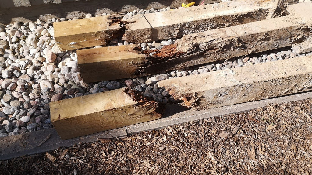
C GARY VAN BOLDEREN — Former CFBA president Gary van Bolderen learned in July that three six-inch-by-eight-inch pressure-treated posts installed to support the roof truss system in a building his firm had built had rotted completely after just 12 years.

Reaction has been swift and stakeholders have swung into action after concerns were raised by former Canadian Farm Builders Association (CFBA) president Gary van Bolderen and others that some types of pressure-treated wood manufactured after 2003 are prematurely rotting in the ground.

In July van Bolderen, now retired as owner of Dutch Masters Construction of Barrie, Ont., received word from a former client that a pole frame building his firm had constructed just 12 years ago was shifting. It was soon determined that three six-inch-by-eight-inch pressure-treated posts, installed to support the building’s roof truss system, had rotted completely.

Since then, van Bolderen and fellow former CFBA president Will Teron, a building engineer who has credentials as a contributor to the National Building Code, have spent hundreds of hours researching the evolution of pressure-treated wood, even visiting a number of lumber yards to determine how well suppliers understood the proper application of the half-dozen or so types of pressure-treated wood that are available.

As a result of their persistence, there was an online call held Nov. 2 involving executives and experts from the Wood Preservation Council (WPC), members of a newly formed CFBA task force and van Bolderen and Teron. Action plans were hatched by both the WPC and the CFBA task force.

Van Bolderen believes the cases he has found in his initial inquiries could be “the tip of the iceberg.”

“As a builder, we don’t know how widespread the actual issue is or how many failures there are going to be, but the problem is, the confidence is gone,” said Brian Brubacher, co-chair with Wayne Blenkhorn of the CFBA task force. “I need to know what I’m buying when I go to my local lumber yard.”

Blenkhorn commented, “I think we have to be careful not to create just general panic…We don’t want everybody to go and be drilling holes in their posts next week.”

The parties have determined the issue stems from a 2003 decision to withdraw certain treatments of pressure-treated products because of fears they caused cancer. When lumber yards stopped stocking that type of wood there was little education on the part of the WPC, the CBFA, manufacturers or distributors to ensure farm builders or other users understood the new set of options and what products were rigorous enough to withstand below-ground use in a commercial building.

That education deficit has continued to today, the stakeholders agree.

Further complicating matters is the categorization of the wood. Teron explained among several standards there are two commercial standards, 4.1 and 4.2, for low-decay and high-decay environments. The WPC is working with the Canadian Standards Association (CSA) to better define those terms, but the residential application has a confusingly similar designation, 4.1 D.

Van Bolderen said he had no complaints of rotting in 50 years until July, with post-2003 wood failing.

“There’s nothing wrong with pole frame as long as it’s the right product. I think there’s a real disconnect between the producer, the retailers, the engineers and the builders about what is the right product,” he said.

“I was absolutely shocked that the posts were deteriorating completely.”

After being alerted to the barn post failures, the WPC developed an initial communication document for CFBA members that defined the different use categories for barn posts and provided an overview on the governing standard, which is CSA 080 for wood preservation.

The WPC will undertake education and outreach that will include a new publication outlining the differences between residential and commercial or industrial pressure treated products and a list of outlets where the proper posts can be obtained.

There will also be webinars held in conjunction with the Canadian Wood Council, and third-party agencies will be consulted, said WPC executive director Natalie Tarini.

The WPC has “recognized that there is a need for education on the various applications and specifications that exist in Canada for preserved wood barn posts,” said Tarini.

“It is important to note that this is a specification/application issue and not a product issue.”

Meanwhile the CFBA task force is preparing an immediate survey for its members to identify other reported failures and other experiences; and it is tracking the changes in treatments over the past 20 years including what supplies are currently being stocked and delivered.

“Clearly our objective is an early advisory to our members of a reported concern that PT posts as used may not be living up to expectation,” said Blenkhorn. “At the same time to establish which products can be manufactured and at what cost to meet this needed life expectancy.

“We feel that we need to send a notice to all the builders now that if you have immediate plans for framing construction, please, please address this with your engineers.”

Teron noted with approval that the WPC is involving technical members of its standards committee and the WPC president.

“We had a really good, frank, direct discussion,” said Teron. “No-one’s pointing fingers. Everyone’s saying we need to move this forward. We need to improve the education so we have an understanding and everyone’s using the effective parts.”

Unheated Post Frame Building Slabs on Grade

Are Unheated Post Frame Building Slabs on Grade Required to Be Frost Protected?

Reader BILL in CLAYTON writes:

“I’m in early planning for a post frame garage – just over 1000 sf but will reduce it if it solves a code problem for “private garages” in IBC. Ignoring that, where does the code permit a slab on ground floor in a post frame building to not be frost protected? Is it not a part of the “building and structure”? Obviously, the floor in most unheated post frame buildings with slabs are not frost protected. In IRC (which Hansen says does not apply to post frame) R301.1 says “Buildings and structures, and parts thereof…” shall be on a foundation and R403.1.4.1 “Except where otherwise protected from frost, foundation walls, piers and other permanent supports of buildings and structures shall be protected from frost by one or more of the following methods:…:” Is a slab on ground floor excluded from “foundation walls, piers and other permanent supports of buildings and structures”? The slab on the ground floor is not a part of the building and structure? Thank you!”

IRC R301.1.3 Engineered design.

“When a building of otherwise conventional construction contains structural elements exceeding the limits of Section R301 or otherwise not conforming to this code, these elements shall be designed in accordance with accepted engineering practice. The extent of such design need only demonstrate compliance of nonconventional elements with other applicable provisions and shall be compatible with the performance of the conventional framed system. Engineered design in accordance with the International Building Code is permitted for all buildings and structures, and parts thereof, included in the scope of this code.”

Unless your site is precluded from having a detached accessory building of over 1000 square feet – my recommendation is to erect the largest building you can afford and fit on your property. Whatever size you build, it will not be large enough. Being over 1000 square feet just means you have an S-2 rather than U classification building and is not going to affect structural design unless your Building Official deems your structure to be Risk Category II, rather than I.

Foundations of most post frame buildings are either embedded columns or columns anchored by approved wet set brackets to concrete piers. A slab on grade, in a post frame building with foundation as described, has no weight of building placed upon it, therefore is not a permanent support of structure.

With this said, Jefferson County is in Climate Zone 6A. As such I personally would follow International Energy Code Table R402.1.2 and place R-10 rigid insulation inside of my splash plank from top of slab (3-1/2″ up from bottom of splash plank) extending downward 48 inches. This can easily be done by trenching at time of construction and would be of benefit should building ever be heated (as most strictly non-agricultural buildings usually are at some point) and be a point in eventual resale.

Barndominium Spray Foam Insulation

What Amount of Barndominium Spray Foam Insulation is Adequate?

Reader DON in LAKE CHARLES writes:

“Building new pole barn. Would using closed cell foam in roof and walls be adequate?”

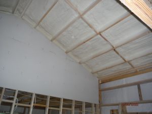
Lake Charles is in climate zone 2A. 2018’s International Energy Conservation Code prescriptively mandates (for your zone) a minimum R-38 value for ceilings and R-13 for wood framed walls. This would require 5-1/2″ in roof and 2″ in walls. You could go with 2″ of closed cell directly to underside of roof deck plus 6″ of open cell, or 2-1/4″ of closed cell with 5-1/2″ of Rockwool as alternatives.

Your state’s Energy Code for Insulation is what your insulation contractor and inspector are looking at, as well as International Building or Residential Code to prescribe what insulation material is safe and efficient to insulate your home. These two codes are used, specifically for prescriptive code, to base how much insulation you need, how it has to be installed, and what insulation materials can be used in certain areas and at what depth. It’s important to note each state has its own insulation code varying depending on climate zone.

You can meet code without having to worry about prescriptive R-Value numbers, through performance.

Performance is more complicated to pass code because your insulation contractor needs to prove his or her insulation creates an air seal, it has an aged R-Value, as well as several different variables. Basically, your insulation contractor is showing your inspector based on numbers and results from testing your insulation will perform efficiently and will also be safe.

Air barriers created by spray foam creates isn’t covered by prescriptive codes, however it passes performance. This is because closed cell spray foam’s air barrier prevents air leakage into and out of your home.

Traditional insulation, like cellulose and fiberglass, will meet prescriptive code when it comes to R-Value, but they still allow for movement of air into and out of your home. This leads to uncomfortable rooms and low energy efficiency.

So, an inspector can’t just take an insulation contractor’s word for it when it comes to how an insulation material performs. This is where testing comes in to help.

Most common way to check a home’s performance is to take all insulation data, room assemblies, etc. and plug those numbers into a computer program.

REScheck is a most popular and common program used when it comes to testing performance. It is so popular because it is fast and easy and once you enter your data, it immediately tells you whether you have passed or failed.

There are other programs out there tending to be more complicated, but are also considered more prestigious.

HERS Index is a measurement of a home’s energy efficiency. HERS is currently a more popular program for checking performance. Many homeowners want a HERS rating for their home because when they go to sell it this rating adds extra value.

Buildings Designed/Built to Code

Designed / Built to Code

Sounds pretty impressive to think you are going to be investing in a new building designed and/or built to “Code”.

Right?

Well – maybe not so much. To begin with “Code” happens to be bare minimum requirements to adequately protect public health, safety and welfare. This does not mean a structure built to “Code” will withstand all possible circumstances. As an example, residential structures (R-3) are designed so as there is a 2% probability of their design loads being exceeded in any given calendar year!

So, how does a consumer best protect their interests?

BE AN INFORMED BUYER

Whether investing in a complete building kit, or having a builder provide materials as well as erection labor – if you receive a proposal stating only “to Code” or not mentioning “Code” at all…..

RUN

All proposals and agreements for buildings should mention what Code and Code version is being used. IRC (International Residential Code) and IBC (International Building Code) do have some differences between them. Every three years there is a new Code version published. Each version has latest updated changes due to testing, research and new products being introduced. Your new building should either match your jurisdiction’s adopted Code version or (if no structural permits are required), most recent version.

ENGINEERING

Unless you are building within prescriptive ‘cook book’ restrictions of a Code, I am a firm believer of buildings being fully engineered. Not just engineered trusses (as an example) but every component and connection being checked and verified by a Registered Professional Engineer specific to your building’s features on your site. This is for everyone’s protection (not just yours, but also your provider and any hired builder).

WHAT TO LOOK FOR ON PROPOSALS AND AGREEMENTS

Beyond applicable Code version, there are other factors you should have included:

Ground Snow Load (Pg) in areas where it snows. Ground snow load is not the same as roof snow load, but is important as it affects drift zones on each side of roof ridges. In these areas, roof purlins often must be closer together, larger dimension or higher graded material to compensate for drifting.

Flat Roof Snow Load (Pf) is usually calculated from Pg and incorporates factors such as Occupancy (low risk buildings get a 20% reduction), wind exposure (an exposed building has snow blow off, a protected site has snow sit) and temperature (heated or unheated and well or poorly insulated). Some jurisdictions mandate a minimum Pf, ignoring applicable laws of physics.

No snow? Then Lr applies, rather than Pf. Lr is a reduced uniformly distributed roof live load ranging from a minimum of 12 to a maximum of 20 psf (pounds per square foot), depending upon the area being carried by a given member.

Design Wind Speed in either V (basic design wind speed, sometimes expressed as Vult) or Vasd, in mph (miles per hour). These values are directly correlated as Vasd equals V multiplied by square root of 0.6.

Wind Exposure – rarely mentioned and extremely important. Most buildings will be on Exposure C sites, meaning they must resist a 20% greater wind force than a fully protected Exposure B site. Become more knowledgeable by reading here: https://www.hansenpolebuildings.com/2012/03/wind-exposure-confusion/

If wind exposure is not delineated on a proposal or agreement, it is not a good sign.

Allowable Foundation Pressure – most people are not interested in having their buildings settle. This value relates to your site’s soil being able to support a given value per square foot of building weight INCLUDING roof and floor live (or snow) and dead (permanent) loads. Keeping it simple, easier to dig equals lower values.  In an ideal world, a geotechnical engineer has tested your site’s soils and can provide an exact measure of soil strength in his or her report. Many providers assume a value of 3000 psf, this would exclude soils including any silts or clays and using this as a value could compromise structural integrity.

Seismic Zone: for single story wood or steel frame structures with low or no snow and more than just bare minimum design wind forces, seismic forces will not dictate structural design. However, they should be checked.

If you are negotiating with a provider or builder who is not clearly stating all of these factors, you are very well paying hard earned money for something you are not getting.

Contact your local jurisdiction so you are aware of what Code minimum requirements are. Ask your provider or builder for any additional investment to upgrade to a greater roof load and/or design wind speed – in most cases it is negligible and it allows you to make informed choices as to risk/reward.

Things You Want to See On a Building Proposal

Things You Want to See on a Building Proposal/Contract

Maybe you (as a soon to be building owner, building contractor or provider) are satisfied with being overly vague when it comes to what you are buying or selling. From a contractor/provider standpoint, this gives you lots of leeway to add ‘extra dealer margin’ by providing minimal (or less than minimal) components to unsuspecting buyers.

Now, my employer happens to offer a “price match guarantee” for any comparable building package. If I had a dollar for every quote from a competitor where it was impossible to even determine what was being proposed to be provided, I would be sitting in a beach chair along an ocean, not writing this article!

Today I am going to address a few highlights, if you are pondering a building investment, you will want to pay close attention…provided getting best investment for your money is important.

Things like building dimensions (width, length, eave height and roof slope) as well as roof style (gable, single slope, monitor, gambrel, dual slope, etc.) might seem to be no brainers, however I find even some of these certainly important features to be overlooked!

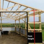
While there does exist an actual ANSI (American National Standards Institute) definition of Eave Height – most builders and vendors are unawares or just plain choose not to use it. Somewhere your agreement should spell out what is proposed or provided so all have a clear understanding. (Please read more here: https://www.hansenpolebuildings.com/2012/03/eave_height/)

Will this building be fully enclosed, partially enclosed or merely a roof? It makes a difference in wind design, so should be clearly delineated.

FEATURES

This is not meant to be a comprehensive list, but is to provide an idea as to how extensive it should be.

Thickness (gauge) of steel roofing and siding, as well as warranty AND substrate should be called out. Caution here as IRC (International Residential Code) Table R905.10.3(2) requires a minimum of AZ 50 for 55% aluminum-zinc-alloy-coated steel (Galvalume) or G-90 for Galvanized steel. These same requirements can be found in IBC (International Building Code) Table 1507.4.3(2). Lesser coatings can only be used for “U” buildings. Will there be wainscot, and if so will there be trim between it and upper wall panels?

How will roof steel condensation be controlled? Not addressing this now will cause challenges later. Integrated Condensation Control (Dripstop or Condenstop), Reflective Radiant Barrier (aka Bubble – and it is NOT insulation), Metal Building Insulation (vinyl faced fiberglass), Sheathing (OSB or plywood) with 30# or heavier felt or a synthetic ice and water shield? Tyvek or other similar housewraps (Weather Resistant Barriers) are not effective for condensation control.

How will any dead attic spaces be ventilated? Soffits, gable, ridge?

If other materials are to be used for roofing and/or siding, specifics as to thickness, quality and warranty should be clearly delineated.

Overhangs – open (no soffit) or enclosed (with soffit). Length of overhangs. Soffit material to be used (vinyl, steel, aluminum) as well as vented or non-vented.

Any overhead sectional or roll-up (coil) doors should be appropriately wind rated. Residential or commercial doors? Smooth faced, long panel or short panel? And glass, and if so, inserts? Specifics as to any manufacturer’s stated R values, thickness of steel, interior backers, track options (standard, low headroom, high lift or with run of roof), color, finish painted or primed only, vinyl weather seals, steel trims on jambs,  openers and operators should be called out.

Entry door width and heights, is door wood, steel, aluminum, vinyl covered, fiberglass? Jambs wood, steel, aluminum, vinyl covered wood? Doors and jambs finish painted or primed only? Crossbucks? Raised Panel? Glass? Wind rated? R value? Keyed lockset, dead bolts?

Windows with dimensions, type of frame material (aluminum, vinyl, composite, etc.), type (sliding, single hung, double hung, fixed, casement, etc.). Glazing (single, double or triple pane, tempered or non-tempered glass). Color of frame. Integrated J channels? Screens? Gas filled? U-factor and SHGC.

Wall framing (girts) external or bookshelf? External girts rarely meet Code deflection requirements and framing will have to be added to create an insulation cavity or apply interior finishes.

Trusses designed to support a ceiling load? If for sheetrock, a 10 psf (pounds per square foot) bottom chord dead load is required.

Future Building Owners – if it is not specifically called out for, do not assume you are getting it. Building providers and contractors – if you are providing a feature and do not call it out, you are doing a poor job of selling yourself.

Our next article will delve into “Code” design requirements – don’t miss out!

Stretching Stick Frame Construction

Post frame (pole building) construction is popular due to efficiencies of materials (ability to do more with less) and speed of construction.

Reader RAYMOND in BARLING is trying to find a way to make stick framing cheaper, he writes:

“24×64 pole barn in question. 4 pitch.  I am just comparing the cost of alternate designs.

Using 2×6 rafters with purlins across top for metal. Can I part from the standard 24 OC of rafters and expand to 30 OC (since more support from purlins)?

Furthermore, is it possible to use 30 OC studs all around, instead of poles (since more support from purlins on walls)

I would really appreciate your wisdom.

Thanks!!”

Mike the Pole Barn Guru says:

Let’s begin with, “since more support from purlins on walls”. Studs in stick framed walls will not resist wind loads perpendicular to a wall any better due to lateral support from purlins (actually girts) installed horizontally.

Your rafters are also going to be unable to support greater roof loads due to purlins being attached.

Building Codes have prescriptive requirements limiting what can and cannot be done with conventional (stud wall) framing, without having to have a fully engineered building. This would include studs and rafters being no greater than 24 inches on center. They also preclude wall heights of over 12 feet (you did not mention any heights however it should be kept in mind).

International Residential Code (IRC) Table R8702.4.1(1) provides rafter spans for common lumber species with a roof live load of 20 psf (this happens to be Code minimum whether snow is present or not). Being as you are in Arkansas, we will assume the minimum load as well as no ceiling being attached to rafters. With rafters 24 inches on center your rafters would need to be 2×8 #2 Southern Pine at a minimum. You would also need to provide ceiling joists or rafter ties to resist outward push of rafters on bearing walls. In order to get full value from rafters, ratio of rafter ties measured vertically above the top of stud walls to the height of roof ridge would need to be 1/7.5 or less. At a 4/12 slope ridge height would be 55.64″ meaning rafter ties could be located no more than 7-3/8″ above top of stud wall, so plan on then being at least 20 feet in length. A ridge board must also be provided as well as a collar tie, gusset plate or ridge strap (please refer to IRC R802.4.2).

Stud walls also mean you would need to make provisions for structural headers above any opening in any load bearing exterior wall. With post frame construction openings can be placed between columns in exterior walls, eliminating structural headers (this assumes trusses are placed aligned with wall columns with roof purlins on edge).

For stud wall construction, your concrete slab on grade will need to have an appropriately thickened edge in order to support weight of walls, or a continuous footing and foundation will need to be poured.

Ultimately post frame construction, not stick wall construction, is most probably going to be Raymond’s best route to go when considering investment and ease of construction.

Arnold Puts Moratorium on Barndominiums

Arnold puts moratorium on ‘barndominiums’

This article by Tony Krausz appeared in the Jefferson County, MO “Leader” October 25, 2020

An example of a barndominium.

The city of Arnold has temporarily prohibited the construction of “barndominiums,” which typically are metal barn-like structures that include living quarters.

City Council members voted 5-0 last month to place a six-month moratorium on building barndominiums inside the Arnold city limits. Ward 1 Councilman Jason Fulbright and Ward 2 Councilman Brian McArthur were absent from the meeting.

The moratorium says no building permits will be issued for the construction of pole buildings, metal-clad buildings and buildings clad with other construction material inconsistent with that of residential development within the city of Arnold, if those structures are intended to be used for residential dwellings.

Twice since March, people have reached out to the city inquiring about building a barn-like structure in Arnold to use as a house, said David Bookless, the city’s Community Development Director.

Currently, the city’s codes do not allow for barndominiums, so during the moratorium, city staff and officials will look at building codes to determine how and where the structures could be built in the city.

“It doesn’t have to take six months,” Community Development Director David Bookless said. “If the Planning Commission figures it out in two months, we are golden, or, if we get to six months and it is a bigger animal than we thought, it could be extended.”

One of the main code violations related to barndominiums is no step up between the living area and the barn or garage area of the structure, Bookless said.

He also told City Council members there are fire risks related to the unique residential structures, as well as risks for the structures to be damaged by seismic or high-wind events.

“We just want to be sure that if any of these come to Arnold that No. 1, they are structurally safe, and No. 2, they are going to be made out of materials and look consistent with the kind of single-family housing that we have in the city,” said Bryan Richison, the city administrator. “That is the whole point.”

During a presentation at a council work session in September, Bookless said barndominiums typically are found in rural areas on large-acre lots.

He said it is possible for someone who wants to construct one in Arnold to spend the extra money needed to meet the city’s buildings codes, which would pave the way for the barn-like homes to be built anywhere in the city.

“Right now, we don’t have design guidance that would stop somebody from building something in a neighborhood that is out of character or context with what is around it,” Bookless said. “If you are in a residential subdivision and there are four models of houses that are typical of a suburb and one house is a pole barn, is that appropriate? That is the type of thing the Planning Commission will discuss.”

Bookless said it is doubtful someone wanting to build a barndominium would want to spend the extra money on construction because part of the appeal is the less expensive construction.

A typical house costs about $115 per square foot to build, while a barndominium costs about $100 per square foot to build, according to the website BarndominiumLife.com.

Bookless said Planning Commission members and city staff will work with city attorney Bob Sweeney to draft an ordinance adjusting codes that would allow the structure to be built in Arnold and will present that to the council.

“There are other communities that have different types of guidelines in place for the design of buildings in commercial and residential areas that have been challenged in court and withstood those challenges,” Bookless said. “We will make sure we utilize the lessons learned from other communities.”

Pole Barn Guru’s comments:

This community has actually not banned barndominiums or post frame homes. Jurisdictional Planning Departments have every right to limit exterior cladding materials and even colors, just not Code compliant structural systems. 


Unless Arnold has enacted a local provision contrary to IRC (International Residential Code), there is no requirement for a step between a garage and a living area – indeed, such a barrier would pose an undue restriction for those who are mobility challenged.

A post frame home fully engineered for R-3 (residential) occupancy would pose less of a risk against extreme climatic conditions than would structures prescriptively constructed under IRC code and a steel exterior skin will be far less likely to be a fire risk than would be vinyl or wood sidings.

A Mezzanine for Your Barndominium

A mezzanine is a common design feature found in all types of buildings- very possibly even your new barndominium, shouse or post frame home. Think of a mezzanine as being a lofted area above a room.

International Building Codes outline some basic rules for mezzanines to help determine if it is an intermediate level within the room it serves or if it is considered another story. 

A mezzanine is an intermediate level between floor and ceiling of any story. In regards to building codes, mezzanines must comply in accordance with IBC (International Building Code) Section 505.2. (Please note all references in this article are 2018 IBC)

Mezzanines can be great features within a building because they provide an additional floor level without being considered an additional story as long as they comply with IBC Section 505.2. Even though they don’t contribute to “building area” or number of “stories” regulated by IBC Section 503.1, they must still be included within “fire area” calculations when determining need for fire protection systems.

Another important piece of information is they should be constructed of consistent materials according to your building’s construction type per IBC Table 601. 

Clear height above and below a mezzanine shall not be less than seven feet.

Total area of a mezzanine within a room shall be not greater than 1/3 floor area of room it is located in (IBC 505.2.1)

Code has some exceptions allowing for a mezzanine to be larger given certain factors such as building’s type of construction and whether the building is equipped with an automatic sprinkler system. IBC 505.2.1 Exception 3 allows for an aggregate area of a mezzanine within a dwelling unit with an approved automatic sprinkler system which can be up to ½ floor area of the room it is located in.

Means of egress (exits) for mezzanines shall comply with applicable provisions of IBC Chapter 10.

A mezzanine acts like a room or space as it has an occupant load. This occupant load must have correct existing parameters per IBC Chapter 10 (egress chapter). IBC Table 1004.5 provides for maximum floor area allowances per occupant. For R-3 (residential) occupancy purposes, this occupant load factor would be 200 square feet per occupant.

A mezzanine shall be open to the room in which it is located, except for walls not more than 42 inches in height.

Code does also provide some exceptions related to mezzanine “openness”. If you meet these exceptions, your mezzanine would not be required to be open. One exception would be if the mezzanine occupant load is not more than 10 (IBC 505.2.3 Exception 1) and another is if it has at least two exits (IBC 505.2.3 Exception 2). In either case you could have an enclosed mezzanine space.

Photos are of the mezzanine within our barndominium. My wife wanted a space within our shouse (shop/house) which would be a totally dedicated space for her sewing and crafts. She has a sign in her sewing loft which clearly states “This is my happy place.” I can tell she is really happy up there as I often can hear her singing along with her favorite rock and roll tunes from the 70’s and 80’s. Lastly, access to her mezzanine is by a wheelchair accessible electric lift system.

Typical Wall Bracing Details for Pole Barns

There are many ways to permanently brace walls of pole barn (post frame) buildings. Most of these methods are utilized in buildings not designed by a Registered Professional Engineer (RDP). A RDP who has a great deal of experience with post frame building intricacies would first be looking at a structural design to utilize steel siding and roofing’s shear strength.

Hansen Pole Buildings’ independent third-party engineers use values obtained from actual full scale testing of steel panels done under supervision and auspices of engineer Merl Townsend: https://www.hansenpolebuildings.com/2012/08/this-is-a-test-steel-strength/. These test results, and those of other tests, are published in the NFBA (National Frame Building Association) Post-Frame Building Design Manual https://www.hansenpolebuildings.com/2015/03/post-frame-building-3/.

Recently reader JOSE from GONZALEZ asked:
“What are the typical wall bracing details for pole barns? Best locations?”

In utilizing steel skin strength, in many cases, needs for other wall bracing is eliminated. This makes for no extra expenses and ease of assembly. When wall bracing is needed, it is usually added closest to corners, where shear load forces are greatest.

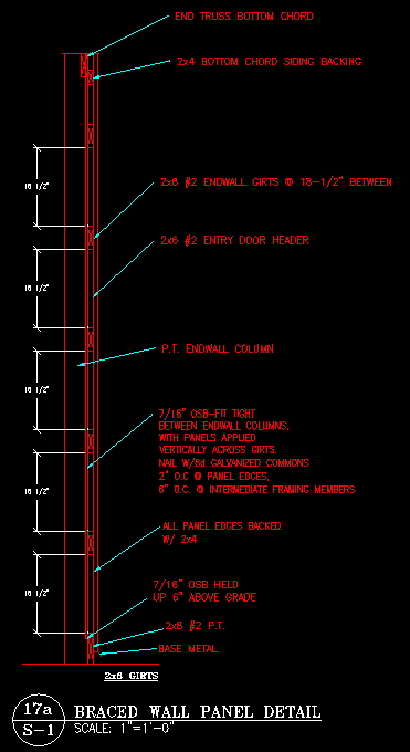
For cases where strength of steel skin is not adequate to support loads, the International Building Code (IBC) provides for wall panels to be braced by adding either Oriented Strand Board (OSB) or plywood. This most often occurs when a wall (or walls) have large amounts of openings (doors and windows) or in cases where buildings are tall and narrow, or very long (usually width of three to four times building length). An engineer can determine the applicability of this as a design solution. Installation of added sheathing is generally fairly simple and requires (in most cases) minimal extra framing materials.

X bracing is often found in non-engineered buildings and can be either of dimensional lumber or steel strapping. Actual effectiveness of either of these is limited by an ability to add enough fasteners to resist loading: https://www.hansenpolebuildings.com/2016/03/diagonal-bracing/.

Rural Renovators recently constructed a very tall post frame building where they utilized a triple set of 2×6 X bracing at building corners: https://www.facebook.com/ruralrenovators/videos/2089528207814164/

In any case, my recommendation for proper post frame building correct structural design is to only use plans designed by a RDP (engineer).

Feedback Needed From RDP’s and Building Officials

I am asking for feedback from RDP’s and Building Officials because:

There is a method to my madness. Seriously. I want to make sure we are doing things 100% correctly. In my humble opinion there are currently numerous post frame buildings being constructed where wall girts do not meet Code or acceptable engineering practice.

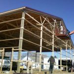
I have developed a professional respect for a builder based in Northern Idaho. Recently I visited his website and saw some photographs leading me to ask about how he solves “barn style” wall girt design issues. He was right on top of it – his photos were of older buildings and he switched to all bookshelf style wall girts years ago, I applaud him for doing so!

Lots of architects, engineers and building officials read my articles, thank you! Your wisdom is appreciated. Attached is an example set of wall girt calculations. If there is an error in any direction, or something missed, your feedback would be more than appreciated. Thank you in advance.

Code is 2015 IBC (International Building Code)

Building Summary

Building Footprint Width 40′
Building Footprint Length 60′
Building Footprint Height 17′
Square Footage (area contained by embedded poles) 2400 ft2
Total Roof Area 2745 ft2
Total Wall Area 3191 ft2
Building Eave Height 17′
Roof Style GABLE
Slope 4/12
Roof Height 20.33′
Building Conditioned Yes

Wind Summary

Vult 110 mph
Vasd 85 mph
Risk Category I
Wind Exposure B
Applicable Internal Pressure Coefficient 0.18
Components and Cladding Design Wind Pressure
Zone 1 -19.78
Zone 2 -32.985
Zone 3 -49.217
Zone 4 -23.522
Zone 5 -27.936
Zone 1 Positive 11.826
Zone 2 Positive 11.826
Zone 3 Positive 11.826
Zone 4 Positive 21.188
Zone 5 Positive 21.188
Duration of Load for Wind 1.6
Structure type Enclosed

wall girt size: 2″X6″
spacing between girts = 22.5″

girt span = 139.875″
supported by 2×4 blocking every 139.875″


Fb: allowable girt pressure
Fb‘ = Fb * CD * CM * Ct * CL * CF * Cfu * Ci * Cr NDS 4.3
CD: load duration factor
CD = 1.6 NDS 4.3
CM: wet service factor
CM = 1 because girts are protected from moisture by building envelope
Ct: temperature factor
Ct = 1 NDS 4.3
Cfu: flat use factor
Cfu = 1 NDS 4.3
Ci: incising factor
Ci = 1 NDS 4.3
Emin: reference adjusted modulus of elasticity
Emin = 470000 psi NDS Supplement
Cr: repetitive member factor
Cr = 1.15 NDS 4.3
lu: laterally unsupported span length
lu = 139.875″
le: effective length
le = 1.63 * lu NDS table 3.3.3
le = 244.496″
CF: size factor
CF = 1.3 NDS 4.3
CL: beam stability factor
CL = 1 NDS 3.3.3
Fb‘ = 850 psi * 1.6 * 1 * 1 * 1 * 1.3 * 1 * 1 * 1.15
Fb‘ = 2033.2 psi

fb: girt test pressure
fb = 6 * 0.6wall_wind_force / 144 * girtSpacing * span2 / 8 / (b * d2) NDS 3.3
fb = 6 * 17.389 psf / 144 in.2/ft.2 * 24″ * 139.875″2 / 8 / (1.5″ * 5.5″2)
fb = 937.255 psi
937.255 ≤ 2033.2 stressed to 46% 6″X2″ #2 OK in bending


Fv‘: allowable shear pressure
Fv = 135 NDS Supplement Table 4-A
Fv‘ = Fv * CD * CM * Ct * Ci NDS 4.3
Fv‘ = 135 psi * 1.6 * 1 * 1 * 1
Fv‘ = 216 psi NDS Supplement

fv: shear girt pressure
fv = 3 * (0.6wall_wind_force / 144 * girtSpacing * span / 2) / (2 * b * d) NDS 3.4
fv = 3 * (17.389 psf / 144 in.2/ft.2 * 24″ * 139.875″ / 2) / (2 * 1.5″ * 5.5″)
fv = 36.854 psi

36.854 ≤ 216 stressed to 17% 6″X2″ #2 OK in shear

Deflection

Δallow: allowable deflection
l = 139.875″
Δallow = 139.875″ / 90
Δallow = 1.5542″
Δmax: maximum deflection
Δmax = 5 * 0.6W * spacing * span4 / 384 / E / I from http://www.awc.org/pdf/DA6-BeamFormulas.pdf p.4
E: Modulus of Elasticity
E = 1300000 psi NDS Supplement
I: moment of inertia
I = b * d3 / 12
I = 1.5″ * 5.5″3 / 12
I = 20.796875 in.4
Δmax = 5 * 12.173 psf / 144 psi/psf * 24″ * 139.875″4 / 384 / 1300000 psi / 20.796875 in.4 components and cladding reduced by .7 per footnote f of IBC table 1604.3
Δmax = 0.37401″ ≤ 1.5542″

A Problem Good Structural Engineering Could Solve Part I

This is copied, by permission, from a blog post by Aaron Halberg, P.E. Aaron is a member of the NFBA (National Frame Building Association) Technical and Research committee.

(In one of the many discussions following the rash of building collapses experienced throughout the Midwest this winter, I received a copy of the email below from Dr. David Bohnhoff, PhD, P.E., Emeritus Professor at the University of Wisconsin – Madison. I reprint it here with the other names removed and with Dr. Bohnhoff’s permission in hopes that his message will reach a wider audience)

“I’m responding to your email and copying a few others on it as I feel the need to get some talking points out in the general public.

For starters the State of WI Uniform Dwelling Code (SPS Chapters 320-325) has absolutely nothing to do with agricultural buildings.  It is a PRESCRIPTIVE code that is only applicable to small buildings.  This would be buildings, for example, whose clearspans seldom exceed 20 or 30 feet.

Larger buildings are structurally engineered in accordance with the governing commercial building code.  In the State of WI, this is a slightly modified version of the International Building Code (IBC) and is referred to as the WI Commercial Building Code (SPS Chapters 361-366).  From a structural design perspective, the IBC is a PERFORMANCE code and it contains verbiage specific to agricultural buildings.  For what could be argued as antiquated (historic) reasoning (more on this later), the State of WI exempts (via SPS 361.02(3)(e))) farm buildings from all provisions of the WI Commercial Building Code.

For reasons (sometimes sheer ignorance) there are a number of builders who believe you can build large buildings in accordance with a PRESCRIPTIVE code for small buildings.

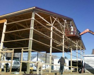
Prescriptive codes are codes that PRESCRIBE exactly what size/grade/shape components to use at various locations and how to connect them.  Prescriptive codes are very limited in their overall applicability.  Prescriptive codes “get by with” using simple, uniformly-distributed loads (e.g., a balanced snow load) to determine component size.  Structural engineers are seldom required when prescriptive codes are in play (and that’s one of the main reasons they exist).

When buildings get large, structural engineering gets more complex.  Most loads are far from being nice and uniform.  Wind and snow patterns are highly variant and quite complex.  When you add in parapets, cupolas, ridge vents, asymmetric roofs, steep roofs, intersecting roofs and associated valleys, overshot ridges, and sudden changes in roof height, AND you combine these with snow that can be blown in any direction, THEN (simply put) you have pages and pages of calculations you better perform if you want both an efficient and safe building.  Calculation of loads and load combinations is the first step in the structural design of a building, and not only are these loads dependent on the size and shape of the building you are designing, but they are also dependent on adjacent structures and terrain.  In many areas of the county, seismic loads are a big part of the equation, and obviously add significantly to the work involved in structural design.

Once the engineer has his loads, he/she begins the process of sizing components AND CONNECTIONS to resist these loads.  To design an efficient structure (in order to keep cost down), the engineer is constantly figuring out (1) ways in which secondary structural components and cladding can best be used to reduce the size of primarily structural components, and (2) ways that components can be connected to reduce component and connection stresses.  This takes both knowledge and experience.  A couple hallmarks of buildings that lack structural engineering are primary framing components that have little or no resistance to buckling, and mechanical connections that have little or no strength because fasteners have been inappropriately sized, spaced and/or located (with respect wood connections, fasteners often induce high wood stresses because they are too close together, too close to the end of a component, too close to the edge of a member, or otherwise used in a manner that induces high tension stress perpendicular-to-grain).

Come back tomorrow as Dr. Bohnhoff continues his discussion of reasons post frame buildings fail due to higher than “normal” snow loads in Part II of a three part series.

Is an Ice Barrier Required Under Post Frame Roofing?

Like a good novelist, I am going to torture you by forcing you to read this story prior to revealing a super- secret answer.

One of our clients will be constructing a Hansen Pole Building in Colorado soon. This particular building is very typical post frame construction as it has steel roofing over open purlins. There is not a “roof decking” of OSB (Oriented Strand Board) or plywood.

When applying for his permit to build his new building, he was told an “Ice Barrier” would be a requirement.

2015 International Building Code deals with a myriad of roofing products in Chapter 15 (check it out yourself here: https://codes.iccsafe.org/content/IBC2015/chapter-15-roof-assemblies-and-rooftop-structures). These include Section 1507.2 Asphalt shingles, 1507.3 Clay and concrete tile, 1507.4 Metal roof panels, 1507.5 Metal roof shingles, 1507.6 Mineral-surfaced roll roofing, 1507.7 Slate Shingles, etc.

Most of these roofing choices list a requirement such as:

“1507.2.8.2 Ice barrier.

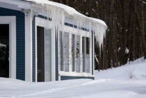
In areas where there has been a history of ice forming along the eaves causing a backup of water, an ice barrier that consists of at least two layers of underlayment cemented together or of a self-adhering polymer modified bitumen sheet shall be used in lieu of normal underlayment and extend from the lowest edges of all roof surfaces to a point at least 24 inches inside the exterior wall line of the building.”

IBC 1507.4 Metal Roof Panels does NOT include a subsection for Ice barrier.

Tim Carter of www.askthebuilder.com explains what ice and water barrier is in this video: https://www.youtube.com/watch?v=yVzF5wE3ptc.

Now it is possible for any local permit issuing authority to make amendments to their adopted version of codes. However if my Building Department had such an amendment I would be asking to see it first, then ask how they propose to install it over widely spaced purlins?

Building Department Checklist 2019 Part 1

BUILDING DEPARTMENT CHECKLIST 2019 PART I

I Can Build, I Can Build!

(First published six years ago, it was more than past time to update to reflect current code requirements!)

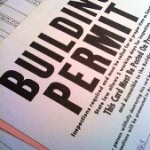
Whoa there Nellie…..before getting all carried away, there are 14 essential questions to have on your Building Department Checklist, in order to ensure structural portions of your new building process goes off without a hitch.  I will cover first seven today, finishing up tomorrow, so you have a chance to take notes, start your own home file folder of “what to do before I build”.  Careful preparation will be key to having a successful post frame building outcome.

#1 What are required setbacks from streets, property lines, existing structures, septic systems, etc.?

Seemingly every jurisdiction has its own set of rules when it comes to setbacks. Want to build closer to a property line or existing structure than distance given? Ask about firewalls. If your building includes a firewall, you can often build closer to a property line. Creating an unusable space between your new building and a property line isn’t very practical. Being able to minimize this space could easily offset the small investment of a firewall. As far as my experience, you cannot dump weather (rain or snow) off a roof onto any neighbor’s lot, or into an alleyway – so keep those factors in mind.

#2 What Building Code will be applicable to this building?

Code is Code, right? Except when it has a “residential” and also has a “building” version and they do not entirely agree with each other. IBC (International Building Code) only applies to post frame buildings, not IRC (International Residential Code:

(https://www.hansenpolebuildings.com/2018/10/what-building-code-applies-to-post-frame-construction/).

Also, every three years Building Codes get a rewrite. One might not think there should be many changes. Surprise! With new research even things seemingly as simple as how snow loads are applied to roofs…changes. Obviously important to know what Code version will be used.

#3 If building will be in snow country, what is GROUND snow load (abbreviated as Pg)?

Make sure you are clear in asking this question specific to “ground”. When you get to #4, you will see why.  Too many times we’ve had clients who asked their building official what their “snow load” will be, and B.O. (Building Official) replied using whichever value they are used to quoting.  Lost in communication was being specific about “ground” or “roof” snow load.

As well, what snow exposure factor (Ce) applies where building will be located? Put simply, will the roof be fully exposed to wind from all directions, partially exposed to wind, or sheltered by being located tight in among conifer trees qualifying as obstructions? Right now will be a good time to stand at your proposed building site and take pictures in all four directions, and then getting your B.O. to give their determination of snow exposure factor, based upon these photos.

#4 What is Flat Roof Snow Load (Pf)?

Since 2000, Building Codes are written with flat roof snow load being calculated from ground snow load. Now design snow load has become quite a science, taking into account a myriad of variables to arrive with a specific roof load for any given set of circumstances.

Unfortunately, some Building Departments have yet to come to grips with this, so they mandate use of a specified flat roof snow load, ignoring laws of physics.

Make certain to clearly understand information provided by your Building Department in regards to snow loads. Failure to do so could result in an expensive lesson.

#5 What is “Ultimate Design” or Vult wind speed in miles per hour?

Lowest possible Vult wind speed (100 miles per hour) only applies in three possible states – California, Oregon and Washington for Risk Category I structures. Everywhere else has a minimum of 105 mph.  Highest United States requirement of 200 mph for Risk Category III and IV buildings comes along portions of Florida’s coastline.  Don’t assume a friend of yours who lives in your same city has your same wind speed.  The city of Tacoma, WA has six different wind speeds within city limits!

Vult and nominal design wind speed Vasd are NOT the same thing. Make certain to always get Vult values.

#6 What is wind exposure (B, C or D)?

Take a few minutes to understand the differences:

(https://www.hansenpolebuildings.com/2012/03/wind-exposure-confusion/).

A Building Department can add hundreds, or even thousands, of dollars to your project cost, by trying to mandate an excessive wind exposure.  Once again, a good place for photographs in all four directions from your building site being shared with your Building Department.  Some jurisdictions “assume” worst case scenarios.  Meaning, your property could very well have all four sides protected and easily “fit” category B wind exposure requirements.  However, your jurisdiction may have their own requirement for every site in their jurisdiction to be wind exposure C, no matter what.  It’s their call.

#7 Are “wind rated” overhead doors required?

Usually this requirements enforcement occurs in hurricane regions. My personal opinion – if buying an overhead door, invest a few extra dollars to get one rated for design wind speeds where the building will be constructed. Truly a “better safe, than sorry” type situation.

I’ve covered seven most important questions for your Building Department Checklist, and they really weren’t so difficult, were they?  Come back tomorrow to find out the last seven!


Plywood Siding Z-Flashing

Plywood Siding Z-Flashing

My first full time construction job was as an MEI (Momb Enterprises, Inc.) slave working for my framing contractor father and his brothers. 1970’s found T1-11 plywood siding to be very popular (as were disco balls) and we installed plenty of it. Where walls were higher than available panels of T1-11, one panel would be installed above another, between each was a thin Z shaped piece of galvanized steel flashing, known appropriately as Z-flashing.

Today’s writing has been spurred by reader GRIFFIN in LONGMONT who writes:

“Is there flashing between the horizontal joints of each T1-11 siding panel?  The inspectors are advising it’s required.”

Mike the Pole Barn Guru responds:

Because I so enjoy terminology such as “inspector said” I used internet power and Google to find a Building Code reference. Closest thing I could find would be this:

From 2015 IBC (International Building Code):

1405.4 Flashing.

Flashing shall be installed in such a manner so as to prevent moisture from entering the wall or to redirect that moisture to the exterior.”

Now common sense would tell me this joint would need to have some sort of flashing to prevent water infiltration in any case. And yes, Hansen Pole Buildings does include Z-flashing where needed for horizontal joints in plywood sidings.

There exists a technique for proper installation:

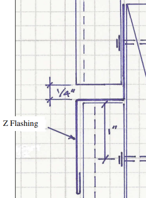
Galvanized Z-flashing, so-called because of its Z-shaped profile, keeps water from getting through horizontal joints between sheets of plywood siding. You set flashing upon top edge of each piece of plywood over a fat bead of caulk and hold it in place with just heads of roofing nails driven into sheathing. Don’t nail through flashing itself or it will eventually leak. Overlap ends of flashing by two or more inches and run a bead of caulk between them. And just before upper plywood panel becomes placed, caulk along top edge of metal as extra protection against water.

While I personally recommend using roll formed steel siding due to its longevity and cost effectiveness, some folks feel plywood siding will be their ideal design solution. For those, we provide proper and appropriate Z-flashing.


Whiskey Tango Foxtrot! Is It Ventilation?

Whiskey Tango Foxtrot! Is it Ventilation?

I really enjoy good food. In order to continue doing so and avoid weighing significantly more than I should, I do a treadmill run nearly every morning. To keep from expiring from utter boredom of exercise, I have wall mounted my flat screen LED television within easy viewing distance. With subscriptions to Amazon Prime and Netflix, I have yet to run out of movies and series to view. Most movie selections are either fairly old, or were box office challenged. One of these movies was 2016’s Tina Fay starring in Whiskey Tango Foxtrot, with a budget of $35 million and a box office take of $18.3 million.

Well, this article isn’t about how Tina Fey carried this movie. To be precise, it’s a movie title conveying my expression upon doing some recent reading.

Back in 2016 I had penned an article (https://www.hansenpolebuildings.com/2015/06/overhang/) mentioning a specific pole building company by name. A representative of this company recently contacted Hansen Pole Buildings’ owner Eric to let him know they did not appreciate being named. I was even kind enough to have included a live link to their website in my article, providing them with free press.

While editing, I happened to peruse their website. When a Whiskey Tango Foxtrot moment hit me…..

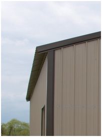
Under ‘Building Features’ I found this gem, “(Our standard roof to eave or gable design creates a fully ventilated structure making boxed overhangs an option, not a necessity)”.

I had to read it several times to fully get my head around what I thought I had read.

In order for this statement to be true, roof steel high ribs would need to remain unobstructed – allowing a free flow of intake air. This could possibly pose a challenge if one desires to keep small flying critters from entering a dead attic space.

In my humble opinion, this attempted ventilation intake ranges from laughable to totally ridiculous. However, I have found, nearly anything can be spun to sound like a benefit. What should be happening between roof steel and eave strut – placement of an Inside Closure (https://www.hansenpolebuildings.com/2015/12/the-lowly-inside-closure/), to seal these openings.

IBC (International Building Code) 2015 Edition tends to agree with me.

“1203.2.1 Openings into attic.

Exterior openings into the attic space of any building intended for human occupancy shall be protected to prevent the entry of birds, squirrels, rodents, snakes and other similar creatures. Openings for ventilation having a least dimension of not less than 1/16 inch and not more than ¼ inch shall be permitted. Openings for ventilation having a least dimension larger than ¼ inch shall be provided with corrosion-resistant wire cloth screening, hardware cloth, perforated vinyl or similar material width openings having a least dimension of not less than 1/16 inch and not more than ¼ inch.”

Thinking about a post frame building other than from Hansen Pole Buildings? Before possibly throwing away your hard earned cash, give us a call – if we feel someone else’s building has a better value than ours, we will be first ones to tell you to invest in it.


Minimum Design Loads and Risk

Minimum Design Loads and Risk

Model Building Codes, such as IBC (International Building Code), offer minimum design loads for climactic forces such as snow and wind. As building permit issuing agencies adopt codes, within their scope they can establish minimum values for their particular jurisdiction.

Key word here “minimum” – least values a building may be designed for and still obtain a permit to build.

I have long been an advocate for structural designs above minimum requirements. All too often potential new post frame building owners have not had adequate consultative design recommendations enough to find out increases in structural strength are often achieved with minimal investment.

For an earlier article concerning this subject please see https://www.hansenpolebuildings.com/2015/11/bike-helmets-and-minimum-building-design-loads/.

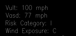
From IBC Section 1604.5, “Each building and structure shall be assigned a risk category in accordance with Table 1604.5. Where a referenced standard specifies an occupancy category, the risk category shall not be taken as lower than the occupancy category specified therein.”

Balance of IBC Chapter 16, including Table 1604.5 may be perused here: https://codes.iccsafe.org/public/document/IBC2018/chapter-16-structural-design.

Buildings representing a low hazard to human life in event of a failure include agricultural facilities. In most jurisdictions, detached garages and shops are also considered to be a fit and these would be considered as Risk Category I. In many areas agricultural buildings are either permit exempt, or do not have to go through structural plan reviews and inspections.  Read a very expensive story about an agricultural building using minimal requirements: https://www.sbcmag.info/content/9/design-load-reductions-risk.

Risk Category I buildings are designed to allow for an occurrence greater than minimum design loads of once in 25 years (or a 4% chance in any given year). In theory, all buildings in this category should collapse within 25 years of construction.

Sobering, isn’t it?

Shopping for a new post frame building and want yours to be last one standing when a storm of a century comes to visit? If so, I would hope whomever you are speaking with offers options of increasing Risk Category from I to II. And bumping up snow loads by 5, 10 or even more pounds per square foot and/or increasing design wind speed by a few more miles per hour.

If you are not offered these options – ask for them. I’d like to have your building be left standing!

Vinyl Gable Vents for Pole Barns

Vinyl Gable Vents for Pole Barns

Attic venting for post frame (pole barn) buildings is a challenge which can be resolved by the use of vinyl gable vents.

Reader KEN in BERRYTON writes:

“I have a pole barn with the ribbed siding, 3/4″ high ribs at 9″ spacing, with two smaller ribs in-between at 3″ spacing.  I need to add end wall gable vents (because I failed to have it built with eaves) because I want to install insulation in the ceiling and walls.  In reading your web information on gable vents, it seems that the vents you offer fit over the ribs as opposed to what I might find at my local Home Depot.  Can you clarify whether the vent you provide fits over the ribs so that I can get a weather tight seal.  If not indexed for the ribs, I am at a loss to understand how you can seal the vent against the ribbed siding.  Any guidance you could share would be very much appreciated.

I also read in a Q/A that dividing the square footage by 300 gives you the number of square inches of vent required.  My building is 60×30 which gives 1800 square feet divided by 300 would be 6 square inches.  I wonder if this is a misprint, that it should be 6 square feet.” 

Mike the Pole Barn Guru responds:

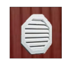
The Hansen Pole Buildings vinyl gable vents are designed with a “snap ring” which goes on top of the high ribs of the steel. To install, remove the snap ring and use the inside edge of it as a template to draw the location of the vent on the siding. Remember to cut just outside of the line, so the vent can be pushed through from the inside. Once it is pushed through, snap on the snap ring and you have a sealed vent! Just this easy and requires no extra framing.

And it is square feet, not inches. In your case you would need to have at least three square feet of net free area venting on each endwall, and it would need to be located in the upper half of the dead attic space. Just as an example an 18″ x 24″ rectangular vent will typically provide about 140 square inches of net free area.

The 2012 IBC (International Building Code) ventilation requirements may be accessed here: https://codes.iccsafe.org/public/document/IBC2015/chapter-12-interior-environment please see 1203.2.


Use and Occupancy Challenge Part II

See yesterday’s blog for Part I. To continue the discussion on Use and Occupancy:
Momentarily skipping a few chapters and going to Chapter 6 (because it would be too simple if the IBC was in order) the code book outlines different types of construction. Post frame buildings can fall under the following construction types:
The Type of Construction for post frame buildings is typically Type V.
602.5 Type V.
Type V construction is that type of construction in which the structural elements, exterior walls and interior walls are of any materials permitted by this code.

Table 601 gives TYPE V-B systems no fire rating (most typical for post frame construction). With a one-hour fire rating for the primary structural frame, bearing walls, as well as floor and roof construction and associated secondary members, post frame buildings could be classified as

TYPE V-A.
In some cases, a post frame building could also be Type III.

602.3 Type III.
Type III construction is that type of construction in which the exterior walls are of noncombustible materials and the interior building elements are of any material permitted by this code. Fire-retardant-treated wood framing complying with Section 2303.2 shall be permitted within exterior wall assemblies of a 2-hour rating or less.

Now head back to Chapter 5.
504.1 General.
The height, in feet, and the number of stories of a building shall be determined based on the type of construction, occupancy classification and whether there is an automatic sprinkler system installed throughout the building.

504.2 Mixed occupancy.
In a building containing mixed occupancies in accordance with Section 508, no individual occupancy shall exceed the height and number of story limits specified in this section for the applicable occupancies.
504.3 Height in feet.
The maximum height, in feet, of a building shall not exceed the limits specified in Table 504.3.

In TABLE 504.3 we find the proposed building to be well under the wall height limitations for Type V-B buildings of 40’ without sprinklers or 60’ with.
504.4 Number of Stories.
The maximum number of stories of a building shall not exceed the limits specified in Table 504.4.

In TABLE 504.4 we find A-3 and U to be limited to one story without sprinklers, or two stories with sprinklers. Buildings with an R-3 category (residence) is three stories without or four stories with sprinklers.

Might the partial second floor be a mezzanine?
“505.2 Mezzanines.
A mezzanine or mezzanines in compliance with Section 505.2 shall be considered a portion of the story below. Such mezzanines shall not contribute to either the building area or number of stories as regulated by Section 503.1. The area of a mezzanine shall be included in determining the fire area. The clear height above and below the mezzanine floor construction shall not be less than seven feet.
505.2.1 Area limitation.
The aggregate area of a mezzanine or mezzanines within a room shall not be greater than one-third of the floor area of that room or space in which they are located. The enclosed portion of a room shall not be included in a determination of the floor area of the room in which the mezzanine is located. In determining the allowable mezzanine area, the area of the mezzanine shall not be included in the floor area of the room.”
If the second floor was 37 feet or less in length it might possibly become a mezzanine, which could alleviate some of the fire separation issues. This is provided the area below is not divided up into individual spaces.

However….
“505.2.3 Openness.
A mezzanine shall be open and unobstructed to the room in which such mezzanine is located except for walls not more than 42 inches in height, columns and posts.
Exceptions:
Mezzanines or portions thereof are not required to be open to the room in which the mezzanines are located, provided that the occupant load of the aggregate area of the enclosed space is not greater than 10.
2. A mezzanine having two or more exits or access to exits is not required to be open to the room in which the mezzanine is located.”
So, it does not appear the second floor will be able to be classified as being a mezzanine.

Come back tomorrow for Part III of a four part series.

International Residential Code and Tension Ties

International Residential Code and Tension Ties

Reader DENNIS in TRAVERSE CITY writes:

“ICC R602.10 is written to work with continuous foundations and vertical studs, not posts in holes and horizontal girts.
How does a person translate bracing into post-frame language?
An answer addressing tension ties would be helpful.”

From the 2015 International Residential Code (IRC):

R602.10 Wall bracing.

Buildings shall be braced in accordance with this section or, when applicable, Section R602.12. Where a building, or portion thereof, does not comply with one or more of the bracing requirements in this section, those portions shall be designed and constructed in accordance with Section R301.1.

R602.12 Simplified wall bracing.

Buildings meeting all of the conditions listed below shall be permitted to be braced in accordance with this section as an alternate to the requirements of Section R602.10. The entire building shall be braced in accordance with this section; the use of other bracing provisions of Section R602.10, except as specified herein, shall not be permitted.

  1. There shall not be more than three stories above the top of a concrete or masonry foundation or basement wall. Permanent wood foundations shall not be permitted.
  2. Floors shall not cantilever more than 24 inches beyond the foundation or bearing wall below.
  3. Wall height shall not be greater than 10 feet.
  4. The building shall have a roof eave-to-ridge height of 15 feet or less.
  5. Exterior walls shall have gypsum board with a minimum thickness of ½ inch installed on the interior side fastened in accordance with Table R702.3.5.
  6. The structure shall be located where the ultimate design wind speed is less than or equal to 130 mph and the exposure category is B or C.
  7. The structure shall be located in Seismic Design Category A, B or C for detached one- and two-family dwellings or Seismic Category A or B for townhouses.
  8. Cripple walls shall not be permitted in three-story buildings.

R301.1 Application.

Buildings and structures, and parts thereof, shall be constructed to safely support all loads, including dead loads, live loads, roof loads, flood loads, snow loads, wind loads and seismic loads as prescribed by this code. The construction of buildings and structures in accordance with the provisions of this code shall result in a system that provides a complete load path that meets the requirements for the transfer of loads from their point of origin through the load-resisting elements to the foundation. Buildings and structures constructed as prescribed by this code are deemed to comply with the requirements of this section.

Please keep in mind, the IRC is a prescriptive code – it calls out the approved methods to put a stick framed building together, within the prescribed load parameters. Post frame (pole) buildings are NOT covered by the IRC, other than:

R301.1.3 Engineered design.

Where a building of otherwise conventional construction contains structural elements exceeding the limits if Section R301 or otherwise not conforming to this code, these elements shall be designed in accordance with accepted engineering practice. The extent of such design need only demonstrate compliance of nonconventional elements with other applicable provisions and shall be compatible with the performance of the conventional framed system. Engineering design in accordance with the International Building Code is permitted for buildings and structures and parts thereof, included in the scope of this code.

Accepted engineering practice and in accordance with the International Building Code  would lead your RDP (Registered Design Professional – Architect or Engineer) to utilize the NFBA (National Frame Building Association) Post-Frame Building Design Manual Second Edition.

While it is possible a design utilizing tension ties could be done, it is probably far more practical to utilize the strength and stiffness of properly fastened steel panels to transfer shear loads from the roof through the endwalls to the ground.

A Wood Floor in a Garage

A loyal reader writes:

“Hi. Good morning! As I read your post about a wood floor in a work shop, it reminded me of my research into a garage with a wood floor. I have often wondered, can this be done?

So I ask you, can this be done?

I am not a rich man, nor do I have much money. I have to be frugal with everything I do and everything I do must be durable and last for a very long time, life hopefully. Hence I am pondering building the things I want in stages.

The size up front will be 16×40. Maybe 20×40 if it’s not much more expensive. Later on, another building attached in the same size dimension ending with a 32×40 or a 40×40.

I would not mind having space in the attic to do things with, but the space I gave you can be used wisely for that anyway.

I will also tell you that I am not what the world considers a young man with a lot of time left on the Earth. I first and foremost need that garage.

I look forward to your answer. I would even like to have a price quote. I live in a mobile home that I once was pondering turning into a house with a garage. But most articles tell me it is not a wise thing to do.

Thank you,
Steven

P.S.- I live in central Alabama. Have a wonderful day!”

Mike the Pole Barn Guru says:

Yes, a garage can be built and designed with a wood floor. Whether or not it should be done is the true question – as it is not going to be an inexpensive proposition.

At my home near Spokane, Washington, I have a post frame garage which is built on a steeply sloping hillside (14 feet of grade change across 24 feet of depth). While the under structure is wood, it does have a concrete slab poured on top of the framing. In hindsight, I would have used fire retardant treated plywood on top of the joists and then sealed the top surface of the plywood. I say this because the concrete slab, in my humble opinion, has not held up as well as I would have liked it to over the past 25 years (it has numerous cracks and sprawls).

The IBC (International Building Code) specifies a uniformly distributed live load of 40 pounds per square foot (psf) (which would be the same as non-sleeping areas of a residence) for garage floors along with the requirement of: “Floors in garages of buildings used for the storage of motor vehicles shall be designed for the uniformly distributed loads of the Table (UBC 1607.1) or the following concentrated loads: (1) for garages restricted to passenger vehicles accommodating not more than nine passengers, 3,000 pounds acting on an area of 4-1/2 inches by 4-1/2 inches.”

This 3,000 pound concentrated load, if it was based upon beams every 12 feet and joists every two feet would equate out to a uniform live load requirement of 125 psf.

Garage floor parking surfaces must be made from approved noncombustible and nonabsorbent materials. FRTW (fire retardant treated wood)might meet with the approval.

Engineered post frame buildings, for any use, are designed to last not only your lifetime, but many lifetimes to follow – so they are a great permanent investment. If the ability to get the most bang for your investment is important, my encouragement would be to borrow a small amount to enable you to get the entire building footprint you ultimately desire, rather than doing the building in two phases. It is always far more economical to do the project once, than in multiple phases and there will be savings both in materials as well as your time to assemble.

Design Wind Speed Changes

Design Wind Speed Changes with Building Code Editions

Every three years a new version of the International Building Code (IBC) is printed, which brings with it the latest and greatest information for building design as approved by Code Officials. State and local permit issuing jurisdictions then can either adopt or amend the Code as they best see fit.

Even though the Code is updated on a three year cycle, some jurisdictions opt to continue to utilize earlier versions of the Code.

Provisions for design loads are set forth in Chapter 16 of the IBC.

There are significant changes to the design wind load requirements for fenestration between the 2009 IBC and the 2012 editions of the same code. These are due to significant changes to the wind load provision of ASCE (American Society® of Civil Engineers) 7 between the 2005 and 2010 edition.

The design wind load provisions of the 2005 and earlier editions of ASCE 7 were based upon allowable stress design of building components. The intent of this method was to provide loads to which the building components had a fairly high likelihood of being exposed during the service life of the building. The building components were then designed to remain serviceable (i.e. not require replacement) when subjected to this load.

The 2010 edition of ASCE 7 provides design wind load provisions which are based upon strength design of building components. This method provides loads which have a lower likelihood of occurring during the service life of the building. The building components are then designed not to fail (rupture) when subjected to this load.

This change in methodology results in higher design wind speeds and pressures. At first glance, this might give the appearance of requiring higher DP (Design Pressure) ratings. In actuality, the 2012 IBC contains provisions to multiply this new, higher load by a factor of 0.6 for the purpose of conversion to the more traditional method of determining the design wind pressure based upon allowable stress design. It is very important the builder, code official, manufacturer and anyone else involved in choosing or approving the structural building design for a particular application understand the higher design wind pressure provided by the 2012 IBC must be multiplied by this 0.6 conversion factor.

In most, but not all, cases this conversion results in required design pressure ratings which are roughly comparable to the more traditionally determined values.

ASCE7-10 also provides three different design wind speed maps. The different maps are based upon the assigned Risk Category of the building being designed.

  1. There is one map for buildings whose collapse would present a low risk to human life, such as barns and storage facilities.
  2. There is a second map for buildings whose collapse is considered to be a moderate hazard to human life. Most buildings fall within this category.
  3. There is a third map for buildings whose collapse is considered a high threat to human life, and for those which are considered essential facilities. The former includes assembly or education buildings designed to house groups of 250 or more people, some medical care facilities and any other buildings designed to house 5,000 people or more. Essential facilities include occupancies such as hospitals and police and fire stations, which are essential during emergency response situations.

The new maps result in higher design wind loads for buildings of moderate hazard to human life than for those of lower hazard. The highest design wind loads are given by the third map for buildings of high hazard to human life and essential facilities. Previous editions of ASCE 7 and the IBC also required these types of buildings to be designed to higher design loads, but the actual increase was applied in a different manner.

Considering a new post frame (pole) building? If you are looking at a building which is NOT designed by a registered design professional (RDP – engineer or architect) then there is an excellent chance the person or persons involved in the design do not understand the changes brought about by the newer editions of the Code and you could end up with an under designed building.

Under design can result in catastrophic failure – or even death. Don’t take the risk, demand an engineered building.

Your life or the lives of your loved ones could be at stake.

Sloping Concrete Floors

Another great and well thought out question, which is best answered at length.

Customizable Workshop for Large HobbiesDear Pole Barn Guru: The construction manual states that concrete slab floors should be poured so there is 3-3/4” of skirt board left exposed above the slab. What do you do if you want or need to have a typical slab slope toward the front of the building? On my 36’ garage that might be around a 4.5” change in slab height from back to front. Since I’m using sheetrock inside (not steel) my thought is that I really only need to have the recommended slab height around my doors at the front of the building to avoid problems and the slab could be poured higher in the back. Appreciate the input! DAN in EVERGREEN

DEAR DAN: The IBC (International Building Code) vaguely addresses this issue: where the minimum per IBC Section 406.1.3 is stated as, “….The area of floor used for parking of automobiles or other vehicles shall be sloped to facilitate the movement of liquids to a drain or toward the main vehicle entry doorway….”.
The command has been given. However the Code does not specifically give an amount of slope. The general consensus is the minimum slope should be 1/8” per foot. This would work out to exactly the 4.5 inches in 36 feet which you had guesstimated.
The important part is to have the top of the slab at door openings be at the 3-3/4” of exposed skirt board left. I’ve come up with different solutions in different buildings of my own. In my oldest, small 22 x 24 garage, the floor is all sloped from front to back. In my two most recent buildings, central floor drains were installed and the floors slope to the drains.

floor-drainI have found I truly like having the floor drains. This allows the floor around the perimeter to all be poured to the same level, which aids in being able to apply inside finishes (such as gypsum wallboard) without the need to custom cut every piece – so it is easier to construct. This also minimizes the overall slope amount, as your 36’ floor could drop the 1/8” per foot in 18 feet for 2-1/4”. By excavating down, instead of having to build up, the amount of compacted fill is reduced (again saving money).
I also happen to live where it is below freezing for more months than I like to think about. By having a central floor drain, I can wash my vehicles in my nice heated spaces and have the wash water go down the drain, as opposed to forming an ice dam in front of my doors.

16 Foot Eave Height and Lofts

We get a few requests for quotes from clients every day – actually more like a few hundred. With this volume of inquiries, it goes to figure we see and hear a broad variety of ideas.

Buildings with lofts
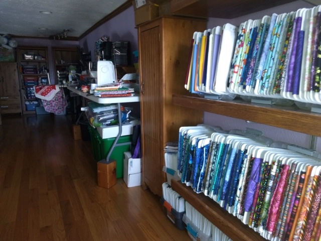
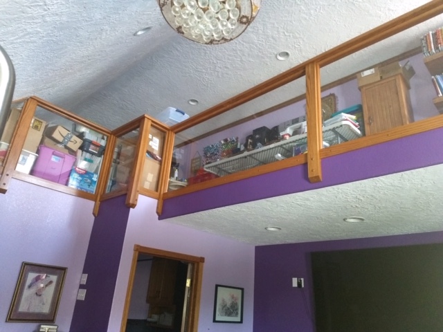
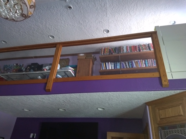
One of the more popular ones is clients who want a 16 foot tall eave height and a loft (either a full or partial second floor).

When I do training sessions for our Building Designers, one of my cautions is folks are generally dimensionally challenged. This particular lofty situation being a case in point.

Most frequently eight foot high ceilings are considered a standard, and allow for two sheets of drywall to be stacked horizontally on a wall without the need to cut sheets lengthwise. The International Codes (IBC – International Building Code and IRC – International Residential Code) do allow for finished ceiling heights as low as 7’6” throughout buildings (as well as seven foot in bathrooms and kitchens), however the lower height increases the amount of work as well as waste.

So, two eight foot high ceilings add up to 16 feet, so a 16 foot eave should be ideal – right?

Wrong.

I’ve had some fun writing about eave height in the past, and you can too by checking out this previous article: https://www.hansenpolebuildings.com/2015/02/eave-height-2/

In our above 8 + 8 = 16 equation, there are a few things being left out. This includes:

A concrete floor – a nominal four inch thick slab on grade is going to chew up 3-1/2 inches when all is said and done;

The thickness of the roof system – as the eave height is measured to the bottom of the roofing, plan upon the loss of at least six inches of thickness to the trusses and roof purlins. If designing for a conditioned (heated and/or cooled) structure, plan upon trusses with “energy heels” https://www.hansenpolebuildings.com/2012/07/raised-heel-trusses/

These could be as deep as nearly two feet in order to allow for R-60 blown in insulation);

Oh, and last but not least, the thickness of the loft floor itself. Most folks who want loft floors would like to minimize the number of supporting columns, so planning upon the loss of a foot minimum. If the floor joists need to span much more than 20 feet (or loads greater than standard residential loads are applied), then engineered wood floor trusses come into play with a general rule of thumb being an inch of depth per foot of span.

From a practicality standpoint, the absolute minimum eave height to allow for two floors should be no less than 18’.

History of a National Design Standard

History of the Development of a National Standard of Practice for Wood Design

NDSFrom time-to-time you might see the term NDS® (National Design Specification® for Wood Construction appear in my blogs, and it is referenced on every set of Hansen Pole Buildings plans, as well as within the International Building Codes.

Me, being the curious sort, wanted to know the history of the NDS® and I was able to find it in the 1997 NDS® commentary. I felt it interesting enough to share:

In the early part of the century, structural design with wood was based on general engineering principles using working stresses or design values published in engineering handbooks and in local building codes. These design values were often not in agreement, even for the same species of wood. Further, on most cases, the assigned values were not related to lumbar grade or quality level.

To meet the growing need for a national standard of practice, the Forest Products Laboratory, an agency of the Forest Service, U.S. Department of Agriculture, prepared a guide for grading and determining working stresses for structural grades of timber.

It provided basic working stresses for clear, straight-grained material of the important commercial species and presented strength ratios for adjusting basic strength values for each species for the effect of any size and location of knots or other natural characteristics permitted in a structural grade. The basic stresses and the strength ratios established in Miscellaneous Publication 185 were based on extensive test data for small, clear specimens and structural timbers obtained from over twenty years of testing and evaluation at the Forest Products Laboratory.

In 1934, the National Lumber Manufacturers Association (now the American Forest & Paper Association assembled the information given in Miscellaneous Publication 185 and working stresses derived therefrom together with engineering equations and other technical information on wood in the publication “Wood Structural Design Data” (WSSD) Included as supplements to the publication was design information for timber fastening. A major component of the WSSD was extensive span and load tables for various sizes of timber beams and columns.

With the initiation of World War II, the need for a comprehensive national design standard for timber structures, including wood connections, became more urgent. The Technical Advisory Committee of the National Lumber Manufacturers Association undertook a more than three year effort to develop the necessary specification in close consultation with the Forest Products Laboratory. The result was The Specification for the Stress-Grade Lumber and It’s Fastening. The Specification included allowable unit stresses fort stress graded lumber, design formulas, and design loads and provisions for timber connector, bolted, lag screw, nail and wood screw joints. Also included were guidelines for the design of glue-laminated structural members.

Despite numerous revisions since 1944, the scope of the Specification has remained essentially unchanged.

To an increasing degree in recent years, the results of research conducted at universities and other private and public laboratories, in Canada and other countries as well as the U.S.have been utilized to improve the Specification as a national standard of practice for wood construction.

In 1992 NFPA (National Forest & Paper Association) was accredited as a canvass sponsor by the American National Standards Institute (ANSI). The Specification subsequently gained approval as an American National Standard with an approval date of October 16,1992.

And there you have it, years of testing and revisions to the Specification, which is the basis for the engineering which goes into every Hansen Pole building kit package.

For those who want or need to know more, visit this website which has the full story of the history of a National Standard of Practice for Wood Design:

https://www.awc.org/pdf/codesstandards/publications/nds/archives/Part00CoverAndHistorypp1to3.pdf

Cross Laminated Timber

And long-time reader Vincent Phelps has another great question: “CBS Sunday morning had a segment on CLT, Cross Laminated timber. It brought timber frame construction to mind. Your thoughts on this technique for the Pole builder?”

https://www.cbsnews.com/news/living-the-high-life/

Cross-laminated timber (CLT) is a large-scale, prefabricated, solid engineered wood panel. Lightweight yet very strong, with superior acoustic, fire, seismic, and thermal performance, CLT is also fast and easy to install, generating almost no waste onsite. CLT offers design flexibility and low environmental impacts. For these reasons, cross-laminated timber is proving to be a highly advantageous alternative to conventional materials like concrete, masonry, or steel, especially in multi-family and commercial construction.

CLT Panel
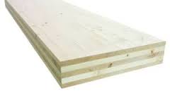
A CLT panel consists of several layers of kiln-dried lumber boards stacked in alternating directions, bonded with structural adhesives, and pressed to form a solid, straight, rectangular panel. CLT panels consist of an odd number of layers (usually, three to seven,) and may be sanded or prefinished before shipping. While at the mill, CLT panels are cut to size, including door and window openings, with state-of-the art CNC (Computer Numerical Controlled) routers, capable of making complex cuts with high precision. Finished CLT panels are exceptionally stiff, strong, and stable, handling load transfer on all sides.

There are some CLT fallacies being circulated:

  • CLT isn’t in the Building Code – wrong, CLT panels have great potential for providing cost-effective building solutions for residential, commercial, and institutional buildings, as well as large industrial facilities in accordance with the International Building Code.  In 2015, CLT will be incorporated into the International Building Code (IBC). The IBC recently adopted ANSI CLT Standard PRG 320 into the 2015 IBC, so you can request a design review based on it now and submit it as an alternate material, design and methods (AMM).
  • It is wood, it burns – Like using a few 12-inch-diameter logs to start a camp fire, mass timber does not catch fire easily. In fact, CLT acts more like concrete. Mass timber is not conventional so it is very hard to light, and once it is lit, it wants to put itself out. A research project recently completed at FPInnovations showed CLT panels have the potential to provide excellent fire resistance, often comparable to typical heavy construction assemblies of non-combustible construction. CLT panels can maintain significant structural capacity for an extended duration of time when exposed to fire.
  • It takes a specialized crew – Keep in mind, CLT is just another form of glue laminated timber (glulam). It is just wood, so it designs and builds on the earlier technology. CLT panels, like other industry panels (precast concrete or SIP panels), provide easy handling during construction and a high level of prefabrication facilitation and rapid project completion.  A conventional wood installation crew with other panel experience can lift, set, and screw down CLT panels, and with a manufacturer provided installation plan, it goes even faster.
  • It isn’t environmentally friendly – CLT is manufactured 2×6 lumber from trees harvested from sustainable managed forests, and mostly Mountain Pine Beetle kill trees. If we don’t use them, they decay and emit carbon back into the atmosphere. Wood is also the only primary structural material which grows naturally and is renewable. In fact, according to “Sustainable Forestry in North America,” during the last 50 years less than 2% of the standing tree inventory in the U.S. was harvested each year, while net tree growth was three percent.
  • It is expensive – When considering the total in-place value of a CLT system, it is cost competitive to other plate building materials. But you also need to consider all the value added benefits.More savings can be found in the reduced installation cost, usually 50% cheaper than installing other plate materials.With an earlier project completion date, you are open for business sometimes months ahead of schedule.

    The building structure will weigh less than half the weight of other construction types, so the foundation costs less money.

  • Job site safety is dramatically increased due to the prefabricated CLT panels and usually the only power tools are pneumatic drills.

The intent of CLT is not to replace light-frame construction, but rather to offer a versatile, low-carbon, and cost-competitive wood-based solution which complements the existing light frame and heavy timber options while offering a suitable candidate for some applications which currently use concrete, masonry, and steel.

My take on your question Vincent – CLT is a pretty neat product, but just like SIPs,

https://www.hansenpolebuildings.com/2015/02/sips/

they are not a practical design solution for most post frame applications.

However, if you want to construct a wooden skyscraper, CLT might be just the thing!

How Long Will a Pole Barn Last?

This was a question asked of Hansen Pole Buildings’ Managing Partner Eric Graff, by one of our Building Designers, Elijah.

To begin with, let’s examine the 2012 International Building Code requirements for the Risk Category of the building.

1604.5 Risk category. 
Each building and structure shall be assigned a risk category in accordance with Table 1604.5. Where a referenced standard specifies an occupancy category, the risk category shall not be taken as lower than the occupancy category specified therein. 

garage-08-0224Most post frame buildings are Risk Category I, as they pose little threat to human life in the event of a failure. These buildings are designed so as the minimum Code Requirements for loading have a probability of being exceeded once in 25 years (a 4% annual probability).

Risk Category II would encompass most homes and commercial buildings with a probability of minimum loadings being exceeded once in 50 years (a 2% annual probability).

Risk Category III and IV are buildings with higher occupancy loads, are defined as essential facilities or ones which would create a greater hazard to human life in the event of a failure. These are designed to a once in 100 year occurrence or a 1% annual probability.

Post frame buildings can fall into any of these categories, so therefore should have basic structural designs and requirements (other than differentiation of applied loads) which are the same for any category.

The perceived ‘weak link’ in post frame construction would be pressure preservative treated columns embedded into the ground. The Code has specific requirements for treated wood (https://www.hansenpolebuildings.com/2012/10/pressure-treated-posts-2/), which (when followed) should provide for a structural system which will be good for a minimum of 100 years, as it would need to make the Risk Category III and IV requirements.

This does NOT mean there will be no maintenance needed to insure a lengthy lifespan.

Roofing and siding products (especially those which are not factory pre-painted steel over galvalume or galvanization) have fairly limited lifespans and will need to be replaced, resurfaced or repainted on a regular basis.

Given the current technologies available for steel roofing and siding paint systems, it is very possible the products which are installed today will yet be serviceable 100 years from now. Granted there is probably a high degree of color fade as well as some probability of rust.

When I inherited my home outside of Spokane, Washington in 1990, the existing cedar post frame garage was still serviceable after more than 50 years of regular use – yes, the untreated columns were showing some signs of decay, but otherwise if we would have owned the two Model A Fords the garage was designed for, it still would have been a nice two car garage.

The definitive answer to Elijah’s question – in all probability any given pole barn building will outlive its intended useful purpose.

Proposed Building Code Change to Add to Construction Costs

During each 3-year-cycle of the International Building Code (IBC) and International Residential Code (IRC), there exists an opportunity to propose modifications and improve the codes to recognize new and innovative construction.  During the final two weeks in April, the code proposal hearings were held in Louisville, Kentucky where several hundred proposals were discussed and considered for inclusion in the code.

large-span-trusses-150x150While post-frame construction is typically used in agricultural applications which are often (and in my humble opinion sadly) considered exempt from code compliance, more and more post-frame construction is either residential housing (IRC) or commercial (IBC) in nature.  In these cases, changes which impact the code may have an effect on how post-frame buildings are constructed.

Eight proposals were identified by NFBA (National Frame Building Association) staff as having a potential impact on post-frame construction.  While the majority of these proposals were defeated, the following action should be noted:

S138-16: Submitted by the Structural Engineers Association, this proposal was approved and will require special inspection for wood trusses with a clear span of 60 feet or greater or an overall height of 60 inches or greater.  While the clear span is not a major issue, the 60 inch height may impact a number of projects creating new cost/scheduling issues.  This change is scheduled to be included in the 2018 IBC.

Having spent my entire adult life installing, designing, selling, building, delivering and purchasing wood trusses, it would seem ludicrous to require a special inspection for wood trusses with an overall height of 60 inches or greater. This would add an extra layer of inspection to nearly every building (not only post frame) project, with seemingly no apparent rationale other than the employment of a large number of people to perform these inspections (most likely the same structural engineers who made this proposal).

Trusses spanning 60 feet or more, are already required to have special inspections, under the IBC: https://www.hansenpolebuildings.com/2013/12/wide-span-trusses/.

What can you do? Contact your local Building Official today and ask them to vote to repeal this costly measure which does little or nothing to improve the safety of buildings.

Building Code & Pole Buildings

When Plans Examiners Try to Apply the “CODE” to Pole Buildings

Today’s example happens to come from the State of Michigan, however it could happen in any Building Permit issuing jurisdiction in the U.S.

What is most interesting to me about this particular example is, last November I was invited to be a presenter at a meeting of Building Officials representing pretty much the northern half of the non-UP (Upper Peninsula) portion of Michigan. The topic was how the Building Codes apply to post frame (pole building) construction, and it was determined as a resultant, the Building Code could not be applied directly.

Building Department
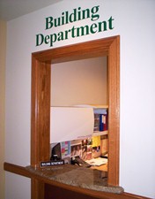
Let’s have some fun with plan reviews, shall we?

(plan reviewer comments in yellow, referenced Code in italics below)

Footing size indicated is too small, (minimum 28″ round x 12″ thick) for sidewalls, or provide load calculations for each column. R403.1 to MBC 1805.7

R403.1 General. 

All exterior walls shall be supported on continuous solid or fully grouted masonry or concrete footings, wood foundations, or other approved structural systems which shall be of sufficient design to accommodate all loads according to Section R301 and to transmit the resulting loads to the soil within the limitations as determined from the character of the soil. Footings shall be supported on undisturbed natural soils or engineered fill.

Following this section of the Code is a Table which gives footing requirements for conventional light-frame construction, 4-inch brick veneer over light frame or 8-inch hollow concrete masonry, or 8-inch solid or fully grouted masonry.

The Code reference does not address footings for isolated, widely spaced columns.

Carrier beam size indicated is too small, three – 2” x 12” carriers minimum, required to carry truss and roof load. Table R502.5 (1)

The Table referenced is for exterior bearing walls in stick frame construction, where the dead load weights of shingles, roof sheathing, and gypsum drywall must be accounted for. It also is based entirely upon ground snow loads, without factoring in the allowable adjustments for this particular building being heated, as well as having a slippery steel roof.

Footnote for most of my readers who are in parts of the country where trusses are attached directly to the columns – this particular pole building is designed with a single truss every four feet, sidewall columns every eight feet and a header (aka “carrier beam”) attached to the columns to support the trusses.

The Table is also based upon a uniform load, which would be applicable for instances where trusses were placed every two feet (ala stick frame construction). Instead the carrier beam, is supporting a concentrated load at the center and every other truss rests directly on top of a column. This effectively reduces the load being carried by the beam by 1/3!

Confused?

Think of the load applied from a truss at two foot centers as being X. In an eight foot area, there would be an X at two, four and six feet or 3X. A truss at four foot only would carry twice as much load as a truss at two feet, or 2X. 2X divided by 3X = 2/3.

Carrier beam nail fasteners are sized too small and additional fasteners are required. Alternate structural screws, lags or bolts may be used. Submit revised fastener design. R 602.2

In my humble opinion, the Plans Examiner meant to reference R 602.3 which lists fastener schedules in Tables. The Tables do not even begin to address the connections found between a “carrier beam” and a column. The Plans Examiner appears to have possibly neglected to note the design presented has the carriers notched into the faces of the bearing columns, resulting in only enough fasteners being required to resist the uplift loads.

Buildings with an eave height 10′ or greater will require knee bracing or a full length diagonal brace in each corner. R301.1.1 to MBC1609.0, 2303.2

R301.1 Design. 

Buildings and structures, and all parts thereof, shall be constructed to safely support all loads, including dead loads, live loads, roof loads, flood loads, snow loads, wind loads and seismic loads as prescribed by this code. The construction of buildings and structures shall result in a system that provides a complete load path capable of transferring all loads from their point of origin through the load-resisting elements to the foundation.

It appears the reviewer’s comments are some sort of a local interpretation of how to handle the requirements of R301.1

I do believe I have previously presented an overwhelming case as to why not to use knee braces: https://www.hansenpolebuildings.com/blog/2012/01/post-frame-construction-knee-braces/

But what about a diagonal brace?

The entire concept of a diagonal brace in a wall is to assume the siding (in this case steel panels), lacks the ability to carry the shear loads being applied to the building.

Having been personally involved in the testing of light gauge steel panels, I can attest to their ability to carry a significant amount of load. (Read more at: https://www.hansenpolebuildings.com/blog/2012/08/this-is-a-test-steel-strength/)

Going back to the assumption of the siding not being able to carry the load, the building being reviewed has 1841.8 pounds of shear force being transferred to each endwall. Keeping things simple, let’s look at what it takes to even attach the suggested braces.

Generously assuming each brace would carry ½ of the applied load, each end of each brace must be able to have a connection adequate to carry around 921 pounds of force. A three inch long 10d common nail (3” x 0.148” diameter) driven through a 1-1/2 inch thick member into another member (assuming the weakest commonly used framing species) will support roughly 128 pounds. It is going to take a lot of nails in a very small area to make the connection work.

To have made this entire process quick, easy and simple for all involved, and to keep the Building Permit issuing authority out of the potential liability problems for being possibly construed as becoming the engineer of record, would be to simply require all pole building plans to be submitted with the seal of a registered design professional (engineer or architect) as well as the supporting calculations.

Which is exactly what this particular client opted to do. Case closed.

Are Building Codes Changed too Often?

(Disclaimer: for those dear readers who are not Christian, the reference to the Bible below is merely for illustrative purposes, and is not an attempt to sway anyone to or from any particular religious practices or beliefs.)

Imagine, if you will, the Bible being revised every three years. Once the revisions were accepted by the scholarly experts and the newest version was printed, each division of Christianity could decide if and when they wanted to adopt the newest version and they could also edit it as they pleased.

Once your church approved a version, it would be up to you and your fellow believers to have to learn it all over again. Sometimes changes would be small, other times large. And about the time you figure it out – there would be another new version.

Sound confusing?

Well, this process is the way the International Building Codes work. Every three years, there is a new version available. Building Officials, Architects and Engineers, as well as builders get to learn everything all over again!

International Building CodeThe NAHB (National Association of Home Builders) and the AIA (American Institute of Architects) have written to the ICC (International Code Council), recommending a longer interval between published Code revisions. The feeling is it would make it easier and less expensive for those affected, as well as easier to manage the changes.

Right now, we have a client who purchased a pole building kit last Spring. When he placed his order, the applicable Code version in his state was the 2009. July 1, his state adopted an amended version of the 2012 Code. He did not apply for his permit promptly, so had to have an entirely new set of plans and calculations produced. Among changes between the versions of the Code, was an increase in design wind speed from 85 to 115 mph (miles per hour)!

While there is some push to increase the time frame between Code versions, it probably will not happen. The reason for frequent changes is the rapid outmoding due to new technologies and building practices.

Think of it this way, a cell phone purchased today will be easily obsolete in three years – same goes for building codes.

What can you do so you don’t end up like our client? Make sure there are no “lag times” between the time you first talk to the building department about what building code design criteria you need to follow, the time you purchase your building, and the time it’s constructed and “final inspection” is done.  And keep in contact with your building department should you encounter any delays.

Why You Need to Verify Design Criteria

Why to Verify Design Criteria

For those of you who are dedicated long term readers, I thank you. I’ve preached this subject more than once – but the message hasn’t gotten through to everyone yet. I will attempt to avoid boring anyone.

There are over 7000 building permit issuing jurisdictions in the United States. A full time employee, calling each of them for their most current code and load information, would need to reach and get data from nearly four an hour – for an entire year, and then it would be time to start all over again!

Each time a Hansen Pole Building is quoted, the design version of the Building Code, as well as all climactic forces the building is designed to, are listed on the pole building quote. Every quote also includes (in bold):

“You must confirm all code/design criteria with your Building Department prior to placing your order. 

We recommend taking this page to your building department for them to verify all design criteria listed above.”

Now my Dad used to tell me, “You can lead a horse to water, and if you hold its head under long enough, it will drown”.

Such may be the case with design criteria. Many clients not only follow instructions, they have done their homework in advance! They have contacted their Building Departments for information, before they even started pole building shopping.

We love these people! They are prepared.

Most of the rest, follow instructions well – they happily contact their Building Department and verify the information before ordering. We love you as well!

Then there are the very small percentage who make assumptions….well, we know where assumptions lead to.

When a post frame building kit package is ordered, one of the items Purchaser agrees to is:

“Seller’s designs rely solely upon occupancy category and structural criteria for and at specified job site address only, which have been provided and/or verified by Purchaser. It is Purchaser’s and only Purchaser’s responsibility to ascertain the design loads utilized in this Agreement meet or exceed the actual dead loads imposed on the structure and the live loads imposed by the local building code or historical climactic records. Purchaser understands Seller and/or Seller’s engineer(s) or agents will NOT be contacting anyone to confirm.”

design criteriaA real life example occurred recently. Client ordered a building kit and thought the roof snow load was to be 35 psf (pounds per square foot). Way too late into the game (prefabricated roof trusses had been delivered to the jobsite) the Building Department tells the permit applicant, “Oops”!

With the right information verified in the beginning, the cost difference would have been minimal. Many times, truss repairs to add five psf of load are fairly affordable. Not in this case – many of the wood members, as well as the majority of the roof truss metal connector plates were originally close to being fully stressed in the original design. For practical purposes, another truss needed to be added to every truss set, in order to meet the slightly higher loads.

Here is a case where ten minutes of the customer’s time to verify, would have saved well over a thousand dollars!

Plan ahead with your design criteria using our helpful Pole Barn Planning Guide.

Building Valuation Data

Every six months the International Code Council (ICC) provides updated Building Valuation Data (BVD) to its members. The BVD table provides the “average” construction costs per square foot, which can be used in determining permit fees for a jurisdiction.

The following building valuation data represents average valuations for most buildings.  Again it should be noted, when using this data, these are “average” costs based on typical construction methods for each occupancy group and type of construction. The average costs include foundation work, structural and nonstructural building components, electrical, plumbing, mechanical and interior finish material. The data is a national average and does not take into account any regional cost differences

The Square Foot Construction Cost does not include the price of the land on which the building is built. The Square Foot Construction Cost takes into account everything from foundation work to the roof structure and coverings but does not include the price of the land.

So……what is a new building’s value?

Private garages are to be valued as an IBC (International Building Code) Section 312 “Group U” utility and miscellaneous structures. V-B is the least restrictive building type with regard to materials. V-B structures can be built out of any material and it doesn’t need to be rated. It is also the most restrictive in terms of size restrictions in IBC Table 503.

A finished V-B Group U structure has a valuation of $39.83 per square foot. If the building is a “shell only”, then 80% of this value would be used ($31.86 per square foot).

Putting up a standard two-car garage 24 feet square? The valuation would be $18,351. A 30’ x 40’ shop? $38,232.

Looking at these valuations, a post frame (pole) building is a tremendous bargain, and a great way to add instant equity to a property! Get a quote on a pole building kit package, add in your other costs (HVAC, etc.) and I believe you will see dollar signs – going into your pocket, instead of out.

Things You Never Wanted to Know About Snow Load

Yes I know, it is white (at least it starts out that way).

From a design standpoint there are lots of things to know about snow loads.

Cautionary Warning: The information contained herein is fairly technical in nature. We use ALL of this information in the design of your new Hansen Pole Building. Some clients will think this is all very cool, for others, it may cause your head to explode. I’ve been waiting three decades to pass along this information to a client, as I’ve always felt the understanding of it is pretty impressive.

1.  GROUND SNOW LOAD (otherwise known as Pg). This is based upon a once in fifty year (probability of event greater than design loads happening is 2% in any given year). The use of unrealistically high Pg values causes issues with the design for drifting snow.

The International Code specifies design snow loads are to be determined according to Section 7 of a document called ASCE 7. This document provides for all roof snow loads to be calculated from ground snow loads, however not every Building Department follows this procedure. When discussing snow load with anyone, it is crucial to have a clear understanding as to if the load is a ground or flat roof snow load.

Pf is FLAT ROOF SNOW LOAD – If, as a consumer, your concern is snowfall and you want to upgrade the ability of your building to carry it, THIS is the value to increase. Often changes of five or 10 pounds per square foot result in minimal differences in cost.

Pg is converted to Pf by this formula:

0.7 X Ce X Ct X Is X Pg = Pf

2. Ce is the wind exposure factor for roofs.

For an Exposure B or C for Wind; Fully Exposed = 0.9; Partially Exposed = 1.0; for fully sheltered (e.g. nestled in tightly amongst conifer trees as an example) Exposure B = 1.2, Exposure C = 1.1 (how you could have Exposure C and fully sheltered is beyond me)

We use partially Exposed (Ce = 1.0 as a default)

3. Ct is the effect of temperature (building heating), where:

Ct = 1.0 for heated structures (climate controlled)

Ct = 1.1 for Structures kept just above freezing and others with cold, ventilated roofs in which the thermal resistance (R-value) between the ventilated space and the heated space exceeds 25h – ft^2 – degreesF/Btu

Ct = 1.2 Unheated

We use Ct = 1.2 as the default value

Most truss designers will use a Ct value of 1.0 or 1.1 in their designs. This results in a decrease in the ability of the roof to carry snow loads. These values should only be used when appropriate.

4. “Is” is the IMPORTANCE FACTOR

ASCE I is a structure which is a low hazard to life in the event of a failure. Is = 0.87

ASCE II residences and frequently occupied commercial buildings (a warehouse or storage building is probably ASCE I) Is = 1.0

ASCE III Is = 1.1

ASCE IV Is = 1.2 (these are “essential” essential facilities – police/fire stations, hospitals)

5. There is also a Minimum Roof Live Load (known as Lr) of 20 psf (defined by Code) (psf = pounds per square foot) which accounts for weights such as construction loads, when Pg values are very low.

Lr is adjusted based upon the area the roof member supports and can be as low as 12 psf, in cases where a roof member supports over 600 square feet of area.

Doing the math, it would be unusual, using the laws of physics, for Pf to be greater than Pg – however, some jurisdictions have established Lr values which defy the laws of physics (e.g. State of Oregon, where most of the state has a minimum Lr of 25 psf – exceptions being some locations along the coast, where it is 20).

From Pf, Pr (Pressure on the roof) values are calculated depending upon whether the roof is a slippery surface or not, whether building is heated or not and the slope of the roof.

The Top Chord Live Load (TCLL) of any roof trusses will be the greater of Pr or Lr.

6. Duration of Load (DOL) for Snow is typically 1.15. DOL can play a part in some snow areas, where the Building Official (BO) has made the determination snow will remain upon the roof for extended time periods. Some Examples of this include Higher elevations in Utah and Kittitas County, WA where the BO has declared DOL = 1.0. In areas with little or no snowfall (where Lr > Pr) DOL = 1.25.

Yes, I know this is a lot of stuff to carry around in your head.  Trust me, I know all too well, and my character analysis consistently reads “does not like numbers”!  All these numbers and “code requirements” are why we not only ask, but insist you must take the page of our quote with the Design Criteria to your building department to get their blessing on it, and ask if there is anything else they require.  With over 7000 building departments in the U.S., it would be the greatest feat on earth if we could keep up with all of them, and which ones change on any given day. My last caution is to be careful when asking your building department about snow load.  Be sure you keep “roof” and “ground” snow loads separate.  Because when it comes to getting your building designed, priced and finally plans signed off by your building department, there is a difference!