Tag Archives: dead loads

Steel Roofing Over Living Areas

 Steel Roofing Over Living Areas Requires Solid Decking?

Barndominiums, shouses and post frame homes have become a recent and trendy rage. Seemingly everyone wants one, at least as gauged by hundreds of weekly requests received by Hansen Pole Buildings would attest to.

Reader STEVEN in BOONE writes:

“I visited with the building inspector with your planning guide and asked if there were any metal roof over living area requirements. IE attach to purlins or deck required. I received an email response that states per IBC 2012 the living space requires a deck first. This seems to defeat the cost savings of using steel and purlins.  Is this correct and if so what materials would be used? Would it be regular roof sheathing? (OSB or plywood be it?) How do pole builders handle the height difference incurred by adding the sheathing. Does this required design change to make trusses closer together in the living area?”

Building inspectors have to deal with not only building codes themselves, but also literally hundreds of referenced titles mentioned within these codes. Thorough knowledge of the contents of this many documents proves to be an impossible task. Your inspector most probably deals with very few residential steel roofs.

From International Residential Code (“R” subsections) and International Building Code (IBC):

R905.10 or IBC 1507.4 Metal roof panels. “The installation of metal roof panels shall comply with the provisions of this section.’

R905.10.1 Deck Requirements. “Metal roof panel roof coverings shall be applied to solid or spaced sheathing, except where the roof covering is specifically designed to be applied to spaced supports.”

IBC 1507.4.1 Deck requirements. “Metal roof panel coverings shall be applied to a solid or closely fitted deck, except where the roof covering is specifically designed to be applied to spaced supports.”

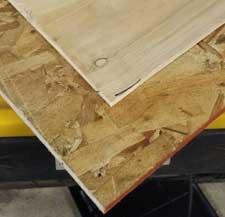
Roof purlins qualify as spaced supports and through screwed steel roofing is designed specifically to be so applied under most wind and snow loads (an exception being hurricane areas of Florida, where a solid deck is required). Properly engineered to support extra dead loads being induced, one could install either plywood or OSB (Oriented Strand Board) sheathing between purlins and steel roofing, using 30# asphalt impregnated paper (felt) or a synthetic ice and water shield. Post frame builders deal with this extra roof thickness by adjusting building eave height downward by sheathing thickness adjusted for slope. Roof truss spacing would not need to be adjusted for sheathing, as purlins will be supporting any underlying sheathing, just as they support your roof steel.

Load Duration Factor in Wood Design

Load Duration Factor in Wood Design

Considering a barndominium, shouse or other post frame (pole) building with wood framing? While this article is somewhat technical, you (as a future building owner) can use it to determine if who (builder or supplier) really knows what they are talking about when it comes to structural design.

And if they cannot answer this one simple question, do you REALLY trust them with your new building?

Here it is:

“Please explain to me Load Duration Factor for Wood Design”.

Please read on.

Lumber has a unique structural characteristic: its ability to handle higher stresses under shorter periods of time. This characteristic is accounted for during design through what is known as a Load Duration Factor (LDF). Given this is a property unique to wood, it is worthwhile for building designers, in a heavily wood-based industry, to fully understand what this factor is and how it can affect their designs. LDF is not applicable to non-wood structural systems. 

Think about loads typically seen in a building. Dead loads are material weights making up a building from the day of construction until it is taken down. Actual dead load and design dead load can be (and often are) different, with design dead load being greater than actual dead load. Building designs can always be performed using actual dead loads when those are well known.

Live loads affect a building less but a portion are still applied through a building’s useful life. Roof live load rarely occurs and when it does, it’s for a very short amount of time. Typical roof live load (not snow, also considered a live load) is walking on roof during repairs, or having a tree fall on your roof. Each of these events are rightly considered short-term loading conditions.

All of this relates to load duration, accumulated amount of time during a building’s life they will be applied. All of these loads are relative to “normal” loading, defined as a “10-year load duration.” 

For reference, live loads are considered normal loads. 2018 NDS (National Design Specification for Wood Construction) Table 2.3.2 shows load duration factors for different durations. This LDF concept is based on engineering mechanics concept of elasticity. Elasticity means when a load is applied to wood it deforms, and when this load is taken off wood it springs back to its original position. Long ago, testing was done at Forest Products Laboratory to give wood a special feature called LDF to account for two things: wood is very elastic; and as more load is applied to wood, more creep deformation occurs over time. 

A good example is bending a yardstick. It can be bent frequently and come back to its original position. However, if you put a weight on a yardstick between two chairs causing it to bend six inches and leave it in this position for six months, what will it look like? 

LDF is a part of Allowable Stress Design (ASD), the analysis method used in wood design for nearly 80 years.

Load Duration Factor Curve shown is taken from NDS Appendix B where more information on LDF can be found.

LDF factor is applied like other loading factors, as NDS design value specified is multiplied by LDF to determine allowable stress. This factor is applicable to bending, tension, shear, and compression parallel to grain reference design values found in NDS Supplement 4. 

What happens if there are multiple load durations within a load case, for example, Dead + Live? Dead load has a load duration factor of 0.9, while normal duration live load (e.g., furniture, beds, people in a room, etc.) has an LDF factor of 1.0. Per NDS this is how LDF is applied:

Hopefully you, like me, want your beautiful new building to structurally withstand what nature throws at it.

What an Engineer of Record Does for a Post Frame Building Part II

Continued from yesterday’s blog, an article by Jesse Lohse in SBC Magazine:


System Design

  • Understand Load Path
    • Gravity
    • Lateral
    • Uplift
    • MEP conflicts
  • Initial Designs
    • Roof System
    • Walls
    • Floor System(s)
    • Foundation
  • Broad Analysis for construction documents

System Design

Once an initial conceptual design is complete, an engineer will turn their attention to system design in a top down manner. An understanding of the structure’s load path is imperative with specific considerations given to gravity loads, lateral loads, and uplift on the various elements within the structure. Once the engineer has a general idea of the structure’s load path, they will begin initial designs of various structural systems. Working from the top down, engineers will produce initial designs first for the roof system. Then the walls including the gravity and lateral force resisting systems and any required beams and columns will be designed followed by the floor systems and repeated as many times as necessary, dependent on the number of levels and different unit types in the structure. Once the roof, walls and floor system has been designed attention will turn to the foundation and footings, leveraging information from the soil report derived in conceptual design. This broad analysis information is compiled into initial structural construction plans.

Element Engineering

  • Accurate dimensions
  • Specific member analysis
  • Coordinate geometry defined in CAD
  • Analysis model created (SAP 2000, STAAD, RAM, etc)
    • Dead loads
    • Live loads
    • Wind loads
    • Seismic loads
  • Internal forces
    • Axial forces
    • Bending moments
    • Shear force
    • Drag force
    • Combined forces
  • Initial Member Sizing

Element Engineering

The element engineering phase begins with the engineer ensuring accurate dimensions for the various portions of the construction project through geometry coordination as defined in 2D or 3D CAD software. Trusting the dimensions are accurate, the engineer will begin specific member analysis for the defined spans, such as calculating roof loads that are transferred to exterior and interior bearing walls. The lateral force resisting systems generally require the most engineering time combine with window and door perforations that require headers and beams. This analysis combines gravity, wind uplift and lateral loads paths. This load path analysis will also be applied to the floor system and foundations, giving the engineer a general idea of the variety of loads within the structural elements and where additional attention will be required in subsequent design phases. To aid in this analysis, engineers will use specific software applications geared towards structural design such as SAP 2000, STAAD and/or RAM. This analysis software will allow the engineer to apply a variety of loads including dead, live, wind and seismic. As a function of this analysis, the engineer will be able to determine axial forces, bending moments, shear force, drag force and the combined forces. Once the forces have been determined, the initial member sizing can commence, allowing the engineer to establish a ‘rough draft’ to further refine in downstream design steps.

Iterative Design

  • Design to code
  • Redesign Analysis model
    • Incorporate more accurate load paths
  • Fine Tune Final Designs

Drafting

  • Create structural plans
  • Fully detailed

Iterative Design and Drafting

Engineer sealed pole barnEngineers use an iterative process to fine tune the various elements into final structural element designs. Think of this as repetitive in nature working toward the ultimate goal of an efficient design that meets the variety of requirements the structure’s configuration places on the path that the applied load will need to take to get to the ground. The engineer starts with a broad understanding of the loads on individual elements and narrows the focus until each element and ultimately the entire structure is designed to safely transfer all loads, meet code requirements and provide an acceptable solution that can be signed and sealed. Through this process the load paths are accurate, specific and reliable. With the accurate load paths, drafting can be completed with fully detailed structural plans available for construction. 

Construction Administration

  • Review submittals
  • Obtain approvals
  • Prepare schedules
  • Monitor construction
  • Perform site inspections

Construction Administration

Further in the construction process, the engineer is often called upon to review RFI and deferred submittals, obtain code approvals or prepare construction schedules. Certain products, such as roof trusses, are considered a deferred submittal. This means the engineer allows the designs to be created by others and sealed by a specialty or delegated engineer.  Those sealed designs are reviewed by the EOR and either approved for manufacture or returned for revisions. Beyond review of conformance to the structural design, engineers will also monitor construction progress on behalf of the client and will often perform site inspections to make sure the construction process is progressing and installation of products is without errors. 


Mike the Pole Barn Guru comments:

Whew! That’s a lot the Engineer of Record does in the design of a post frame building. This whole process takes time and sometimes even I can get impatient while waiting for building plans to be produced and signed by the Engineer. But I know given adequate time the plans will be accurate and result in a beautiful post frame building.

What does 2×6 Lumber Weigh?

Is 2×6 lumber heavy?

ScaleThis is actually fairly important, not just to determine how many boards can be toted around a jobsite by one person, but also in calculating the dead loads which must be carried by structural members such as roof trusses and rafters.

Like most things played around with by engineers, and other people with too much time on their hands, there is a formula to calculate this (please feel free to scream in anguish now):

62.4 X [ G / (1 + G X 0.009) X (m.c.)] X [1 + m.c./100]

Whoo Hoo!! If this isn’t fun…..like watching paint dry?!

Seriously, it is not so tough. G is the value of the Specific Gravity of a known species of lumber. In the U.S. the most popular choices for framing lumber are Southern Pine (G=0.55), Douglas Fir-Larch (G=0.50), Hem-Fir (G=0.43) and Spruce-Pine-Fir (G=0.42).

The moisture content of the lumber is expressed as the “m.c.” above. Lumber stamped as “dry” has a maximum moisture content of 19%.

Picking Dry Hem-Fir and filling the appropriate blanks into the formula gives, 62.4 * [.43 / (1 + .43 * 0.009 * .19)] * [ 1 + (.19/100)] = 26.86 pcf (pounds per cubic foot).  So a 12 inch cube of dry Hem-Fir should weigh 26.86 pounds.

A cubic foot has 1728 cubic inches (ci). 2×6 has finished dimensions of 1-1/2 inches by 5-1/2”, or 99 ci in lineal a foot. Taking the weight calculated above (26.86 pcf) dividing by 1728 and multiplying by 99, gives the weight of a foot of Hem-Fir 2×6 as 1.539 pounds (lbs).

Want to pack around 12 foot long 2×6 lumber? In Hem-Fir, it will weigh 18.466 lbs.

Think of dead loads as the weights of materials which are permanent. In the case of a typical pole barn roof, purlins will always be there supporting the roof sheathing.

If purlins are placed two foot on center, up the slope (or run) of the roof, the dead load attributed to the purlins can be determined by dividing the weight per lineal foot (1.539 lbs calculated above) by the spacing of the purlin (in feet) divided by the cosine of the roof slope. In this case, it is roughly 0.81 psf (pounds per square foot).

Not a lot of weight, but it still must be accounted for. As well, 60% of dead load weight can also be used to counteract the forces of uplift.

So much for the math lesson of the day.

Now, aren’t you glad you asked?