Some of you are familiar with my talking about when my son was very young he asked me what it was like to play Nintendo by candlelight. While I’ve got a few gray hairs, contrary to popular belief, Honest Abe and I did not play Mario Brothers together.
Back in the day when I managed the roof truss manufacturing operations for Lucas Plywood and Lumber, in Salem, Oregon, we had an interesting request for pole building trusses from a builder. Now this was before I really had any understanding of how post frame buildings worked (we are talking about the 1970’s), so it all seemed Greek to me.
 In this particular case, the builder wanted trusses which would be spaced two every 12 feet. Nothing unusual there. This was and is, fairly typical of post frame buildings in the western United States. 32 foot in span, standard 4/12 roof slope, there was nothing unusual about the roof loading.
The unusual part – the trusses would have bearing points only at one end, and directly in the center! Now I had never heard of such a thing, but the trusses did engineer out, we got the order, built and delivered the trusses.
I, being the curious sort, wanted to know how the heck they were being used. The pole builder we sold them to explained they were for an airplane T hangar at the Chehalis, Washington airport.
Here is how he explained how it all worked for the airplane T hangar design (please feel free to take out a sheet of paper and follow along at home):
Draw a row of ten equally spaced dots left to right across a sheet of paper. Draw another identical row directly above and below this row, spaced slightly further apart than from the original line than the dots in the first row.
Now play “connect the dots”. Starting in the lower left corner, go up a dot, then right a dot, up a dot, right a dot, down a dot, right a dot, up a dot…..See a pattern forming? Well, just keep on repeating until arriving at the end of the row.
Next, erase a few dots – working from left to right again, dots 4,5,8 and 9 of the top row, and 2,3,6 and 7 of the bottom row are eliminated.
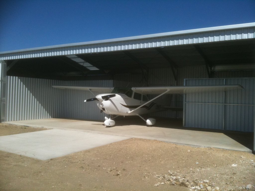
Done right, four T’s have been created. In the case of the building above, each T area could handle a plane with a wingspan just under 36 feet and a depth of 32 feet (the dots left to right each represent 12 foot spacings and the rows representing 16 feet apart).
The overall building length could be increased by 24 feet to add space for one more plane, or 36 feet for two. This system works very well for airports where planes can taxi to either side of the building, as well as where building length is not a big issue.
In tomorrow’s blog, some of the challenges of this airplane T hangar design come in to play in real life.


Interested in A 240 t hangar in Ga for up to 12 aircraft. Thanks Wayne
Thank you for your interest in a new Hansen Pole Building, one of our Building Designers will be reaching out to you shortly, or call 1.866.200.9657 for immediate service.